


72
4
4
4
4.
.
.
.4
4
4
4
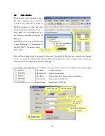
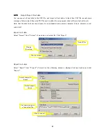
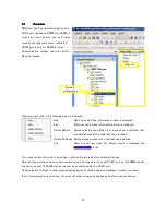
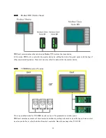
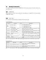
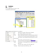
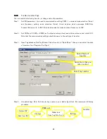
Monitoring of communication
Monitoring of communication
Monitoring of communication
Monitoring of communication
You can check communication status by POWER LED (refer
2.6) and system tag. These system tags can be
used in ladder block.
4
4
4
4.
.
.
.3
3
3
3.
.
.
.1
1
1
1
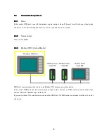
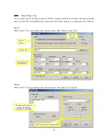
POWER LED
When COM port is set to the communicating and communicating error is detected or not communicating,
POWER LED is blinking.
4
4
4
4.
.
.
.3
3
3
3.
.
.
.2
2
2
2
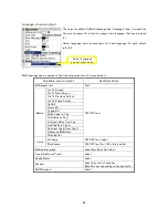
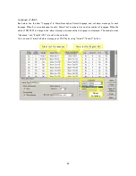
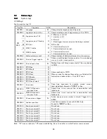
System tags
You can monitor communication status in ladder block by using system tag.
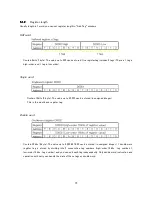
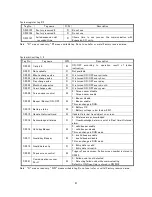
System Registers
Tag No.
Tag name
R/W
Description
_14
COM 1 status
R
0 = Communication error
1 = Communication is normal.
SW
0003
_15
COM 2 status
R
0 = Communication error
1 = Communication is normal.
SW 0018
Communication
recover
scan time for COM 1
R
Shows time in sec recover the communication with
failed node. Default value is 60 Sec.
SW 0019
Communication
recover
scan time for COM 2
R
Shows time in sec recover the communication with
failed node. Default value is 60 Sec.
SW 0064 -
SW 0065
Node status register for
COM 1
R
Shows the status of the node, whether node is COM 1
present or not. Total 2 word Register are mapped for 32
nodes.
SW 0080 -
SW 0081
Node status register for
COM 2
R
Shows the status of the node, whether node is COM 2
present or not. Total 2 word Register are mapped for 32
nodes.
Note : “R” means read only, “R/W” means writable tag. Do not use (refer or write) Factory reserved area.
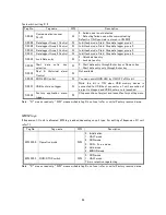
System Bit/Coil
Tag No.
Tag name
R/W
Description
S 0021
COM 1 failed node reconnect
R/W
Failed node is detected and reconnected.
Default is ON (1).
S 0022
COM 2 failed node reconnect
R/W
Failed node is detected and reconnected.
Default is ON (1).
Note : “R” means read only, “R/W” means writable tag. Do not use (refer or write) Factory reserved area.
Summary of Contents for TR PMIU
Page 11: ...1 Chapter Chapter Chapter Chapter 1 1 1 1 Introduction Introduction Introduction Introduction ...
Page 15: ...5 Chapter 2 Chapter 2 Chapter 2 Chapter 2 Hardware Hardware Hardware Hardware ...
Page 23: ...13 Input Wiring for TR PDIO0808 P Output ...
Page 24: ...14 Wiring for TR PDIO0808 N Input Output ...
Page 26: ...16 Input Input Wiring for TR PDIX1600 ...
Page 28: ...18 Output Wiring for TRSDOX0016N ...
Page 39: ...29 Chapter Chapter Chapter Chapter 3 3 3 3 TR PGMS TR PGMS TR PGMS TR PGMS ...
Page 83: ...73 Chapter 5 Chapter 5 Chapter 5 Chapter 5 Tag Tag Tag Tag ...
Page 98: ...88 Chapter Chapter Chapter Chapter 6 6 6 6 Task Task Task Task ...
Page 124: ...114 Chapter 8 Chapter 8 Chapter 8 Chapter 8 Screen Screen Screen Screen ...
Page 167: ...157 Note for the numbers of alarm message ...
Page 176: ...166 Appendix Appendix Appendix Appendix ...
Page 181: ...171 ...
Page 182: ...172 ...