


22
Lock
Lock
2
2
2
2.
.
.
.4
4
4
4.
.
.
.4
4
4
4
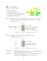
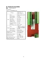
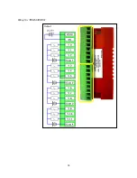
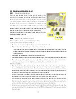
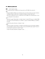
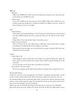
Installation of Expansion I/O unit
Installation method is common to all expansion I/O units. Installation slot position of the expansion I/O unit is
free. You can install expansion I/O unit in an arbitrary slot.
Before installing expansion I/O unit, turn off power supply of the unit. To prevent accident, attach slot cover to
the connector of the extended slot not used.
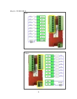
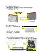
Step 1.
Slide lock
All Expansion I/O units have 2 locks and 2 positioning
pins. At first, slide locks to outside.
Step 2.
Install Expansion I/O unit to TR PMIU unit
Remove slot cover of PMIU unit, then the expansion connector appears. Check connector position of
expansion I/O unit, fit unit to position with the connector and positioning pin, push into expansion I/O unit,
then slide lock to inside.
Do not push expansion I/O unit forcibly, note that the connector is correctly connected.
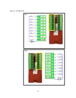
Lock
1
1
1
1
. Remove
Slot cover
3
3
3
3
. Insert Expansion unit
2
2
2
2
. Check Connector
4
4
4
4
. Lock
4
4
4
4
. Lock
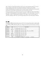
Summary of Contents for TR PMIU
Page 11: ...1 Chapter Chapter Chapter Chapter 1 1 1 1 Introduction Introduction Introduction Introduction ...
Page 15: ...5 Chapter 2 Chapter 2 Chapter 2 Chapter 2 Hardware Hardware Hardware Hardware ...
Page 23: ...13 Input Wiring for TR PDIO0808 P Output ...
Page 24: ...14 Wiring for TR PDIO0808 N Input Output ...
Page 26: ...16 Input Input Wiring for TR PDIX1600 ...
Page 28: ...18 Output Wiring for TRSDOX0016N ...
Page 39: ...29 Chapter Chapter Chapter Chapter 3 3 3 3 TR PGMS TR PGMS TR PGMS TR PGMS ...
Page 83: ...73 Chapter 5 Chapter 5 Chapter 5 Chapter 5 Tag Tag Tag Tag ...
Page 98: ...88 Chapter Chapter Chapter Chapter 6 6 6 6 Task Task Task Task ...
Page 124: ...114 Chapter 8 Chapter 8 Chapter 8 Chapter 8 Screen Screen Screen Screen ...
Page 167: ...157 Note for the numbers of alarm message ...
Page 176: ...166 Appendix Appendix Appendix Appendix ...
Page 181: ...171 ...
Page 182: ...172 ...