


138
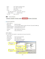
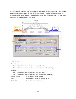
Historical Trend
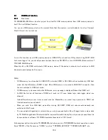
This object can be used only when data logger is set. Refer
9.5.
Display of this object is not refreshed automatically. When you refresh display, turn ON system coil tag S 0012
(Update the Historical Trend). The display is updated in rising edge of turn ON. If you refresh display periodically,
implement task or ladder logic to ON/OFF this bit periodically.
Note that at a moment of display refresh, scan time is extended because processing load for display. Refresh
interval more than 5 seconds is recommended.
・
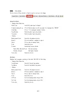
Appearance
Background Color
Set background color of object.
Error Message Font Color
Set the color of error message font.
Font
Set font size.
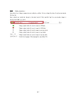
Grid
If No, grids of graph area are not displayed.
Grid color
Set grid color.
Label
If Yes, display label of object.
Label Font
Set label text font.
Label Text Color
Set label text color.
Language
Select display language of object.
・
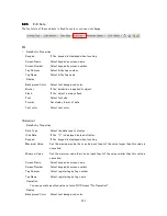
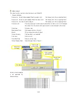
Tag Attributes
This object can display only the data that logged by data logger. Available tag is only the tag set in a data logger.
Data Type
Select referred data type.
Number of Tags
Set number of tag that you display. Up to 4.
Selected Tag Color
Set display color of selected tag.
Tag
Set number of selected tags.
Tag Address
Select the register tag to display by tag number.
Tag Name
Select the register tag to display by tag name.
・
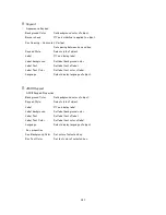
Time Scale Properties
Number of Grids
Set number of X (time) axis grid.
Scale
If Yes, display scale.
Scale Color
Set color of scale.
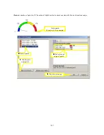
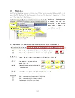
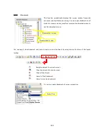
Start/End Time Tags Settings
Start Tags set the date/time of left edge of time axis, End tags set the
date/time of right edge of time axis. Object displays the data between Start
time and End time as line graph automatically.
If there is any error in this property, data is not displayed and error message is
displayed to bottom of object. Set the register tags to set the display of time
scale. Refer next page.
Summary of Contents for TR PMIU
Page 11: ...1 Chapter Chapter Chapter Chapter 1 1 1 1 Introduction Introduction Introduction Introduction ...
Page 15: ...5 Chapter 2 Chapter 2 Chapter 2 Chapter 2 Hardware Hardware Hardware Hardware ...
Page 23: ...13 Input Wiring for TR PDIO0808 P Output ...
Page 24: ...14 Wiring for TR PDIO0808 N Input Output ...
Page 26: ...16 Input Input Wiring for TR PDIX1600 ...
Page 28: ...18 Output Wiring for TRSDOX0016N ...
Page 39: ...29 Chapter Chapter Chapter Chapter 3 3 3 3 TR PGMS TR PGMS TR PGMS TR PGMS ...
Page 83: ...73 Chapter 5 Chapter 5 Chapter 5 Chapter 5 Tag Tag Tag Tag ...
Page 98: ...88 Chapter Chapter Chapter Chapter 6 6 6 6 Task Task Task Task ...
Page 124: ...114 Chapter 8 Chapter 8 Chapter 8 Chapter 8 Screen Screen Screen Screen ...
Page 167: ...157 Note for the numbers of alarm message ...
Page 176: ...166 Appendix Appendix Appendix Appendix ...
Page 181: ...171 ...
Page 182: ...172 ...