


158
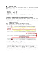
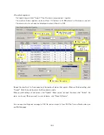
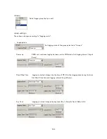
16 consecutive registers
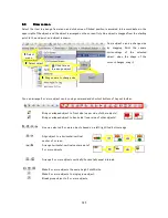
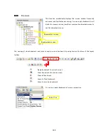
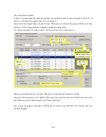
If there is 16 register tags that addresses continue, the top address of these tags is displayed in "Tag List" (If
there is no 16 consecutive register tags, it is not displayed).
Select the head of register tags and click “Assign”. 256 alarms are automatically prepared. If the bit of these
registers is ON, corresponding alarm message is displayed to alarm object.
You need not necessarily use all the alarms, but these cannot use for other purpose.
When you finished setting, click “Accept”. Note that only the alarm that Accepted is enable.
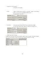
When you edit existing alarm, click “Update”. When you do not need the alarm, click “Delete”, the alarm is not
used. When you want to reset all alarms, click “Reset All Alarms”.
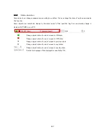
You can export settings and message to CSV file, and can import it from CSV file. This is effective when you
use Multi language.
1
1
1
1
. Select Head of
alarm registers
2
2
2
2
. Click “Assign”
3
3
3
3
. Select
alarm
5
5
5
5
. Click
“Accept”
4
4
4
4
. Set Alarm Description.
6
6
6
6
. Accepted alarm
is displayed in blue.
Summary of Contents for TR PMIU
Page 11: ...1 Chapter Chapter Chapter Chapter 1 1 1 1 Introduction Introduction Introduction Introduction ...
Page 15: ...5 Chapter 2 Chapter 2 Chapter 2 Chapter 2 Hardware Hardware Hardware Hardware ...
Page 23: ...13 Input Wiring for TR PDIO0808 P Output ...
Page 24: ...14 Wiring for TR PDIO0808 N Input Output ...
Page 26: ...16 Input Input Wiring for TR PDIX1600 ...
Page 28: ...18 Output Wiring for TRSDOX0016N ...
Page 39: ...29 Chapter Chapter Chapter Chapter 3 3 3 3 TR PGMS TR PGMS TR PGMS TR PGMS ...
Page 83: ...73 Chapter 5 Chapter 5 Chapter 5 Chapter 5 Tag Tag Tag Tag ...
Page 98: ...88 Chapter Chapter Chapter Chapter 6 6 6 6 Task Task Task Task ...
Page 124: ...114 Chapter 8 Chapter 8 Chapter 8 Chapter 8 Screen Screen Screen Screen ...
Page 167: ...157 Note for the numbers of alarm message ...
Page 176: ...166 Appendix Appendix Appendix Appendix ...
Page 181: ...171 ...
Page 182: ...172 ...