

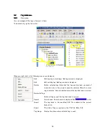


84
5
5
5
5.
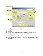
.
.
.3
3
3
3.
.
.
.3
3
3
3
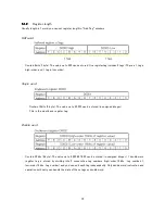
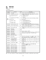
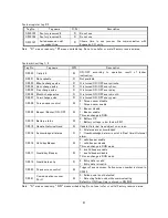
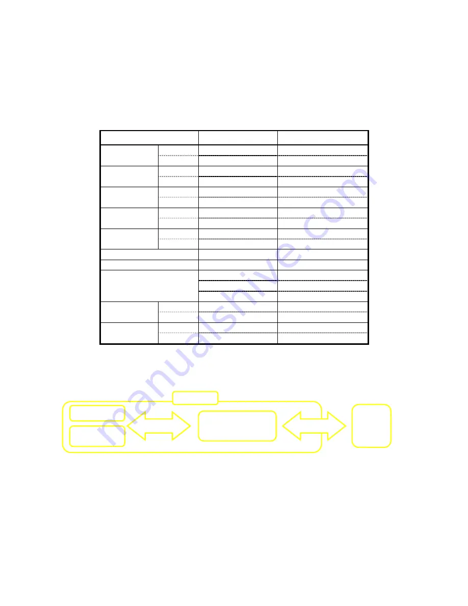
Modbus Tags
You can control/monitor other communicating devices by writing/referring these tags (If you set the port as
Modbus slave, you cannot define these tags. Refer
4.3.3).
Modbus address is shown as follows. To make easily to see, space is put. Do not put space when you actually
input it. And, note that Modbus address starts from "1".
There is a limitation in the place where you can use the tag for (For example, Modbus tags cannot be used in
the ladder block.). We recommend copy data onto internal tag or data register by a Global task.
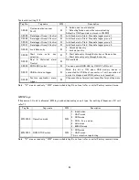
Tag type
Address in unit
Address in Modbus
Coil
X 0000 – 6399
00 00 01 – 00 64 00
Input
Register
X W0000 – 0400
44 00 01 – 44 03 99
Coil
Y 0000 – 6399
01 00 01 – 01 64 00
Output
Register
Y W0000 – 0400
44 10 01 – 44 13 99
Coil
T. 0000 – 0255
02 10 01 – 02 12 56
Timer
Register
T 0000 – 0255
40 00 01 – 40 02 56
Coil
C. 0000 – 0255
02 20 01 – 02 22 56
Counter
Register
C 0000 – 0255
41 00 01 – 41 02 56
Coil
B 0000 – 4095
03 00 01 – 03 40 96
Internal
Register
BW 0000 - 0255
44 20 01 – 44 22 56
Data register
D 0000 – 4095
45 00 01 – 45 40 96
Retentive register
R 0000 – 1399
43 00 01 – 43 14 00
I 0000
44 30 01
J 0000
44 30 02
Index Register
K 0000
44 30 03
Coil
M 00000 – 25600
03 50 01 – 06 06 00
Configuration
register
Register
MW 0000 – 1600
46 00 01 – 46 16 00
Coil
S 0000 - 0099
02 00 01 – 02 01 00
System tags
Register
SW 0000 – 0256
42 00 01 – 42 02 56
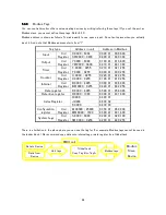
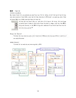
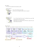
Global task
Copy Tag B to Tag A
Modbus
Slave
Device
Data to Decice
Data from
Decice
Unit tags
Modbus tags
PMIU unit
Summary of Contents for TR PMIU
Page 11: ...1 Chapter Chapter Chapter Chapter 1 1 1 1 Introduction Introduction Introduction Introduction ...
Page 15: ...5 Chapter 2 Chapter 2 Chapter 2 Chapter 2 Hardware Hardware Hardware Hardware ...
Page 23: ...13 Input Wiring for TR PDIO0808 P Output ...
Page 24: ...14 Wiring for TR PDIO0808 N Input Output ...
Page 26: ...16 Input Input Wiring for TR PDIX1600 ...
Page 28: ...18 Output Wiring for TRSDOX0016N ...
Page 39: ...29 Chapter Chapter Chapter Chapter 3 3 3 3 TR PGMS TR PGMS TR PGMS TR PGMS ...
Page 83: ...73 Chapter 5 Chapter 5 Chapter 5 Chapter 5 Tag Tag Tag Tag ...
Page 98: ...88 Chapter Chapter Chapter Chapter 6 6 6 6 Task Task Task Task ...
Page 124: ...114 Chapter 8 Chapter 8 Chapter 8 Chapter 8 Screen Screen Screen Screen ...
Page 167: ...157 Note for the numbers of alarm message ...
Page 176: ...166 Appendix Appendix Appendix Appendix ...
Page 181: ...171 ...
Page 182: ...172 ...