


3
Important term of operation
About detail of each term, refer later chapter.
Tag
Tag is all registers or devices addressed in all TR series unit or other devices communicating with
PMIU unit. There are much kind of tags corresponding to data type (Bit, numerical data, retentive
area, system setting, etc). All the tags of a current project are registered in Tag Database. You can
refer/add/edit/remove tag from here. Refer
5.1.
Task
Task is defined operation and is executed specific timing. All the tasks of a current project is
registered in Task list corresponding to execution timing. Refer
6.1.
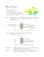
Download/Upload/Online
The transfer of project data from your PC to PMIU unit is called “Download”, the transfer from PMIU
unit to your PC is called “Upload”. You can monitor edit tags of PMIU unit in RUN mode, it is called
“ONLINE” mode. Refer
3.2.4.
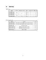
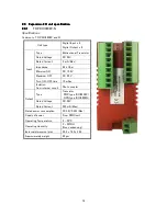
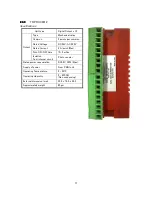
PMIU unit/Expansion I/O unit
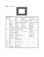
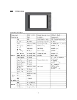
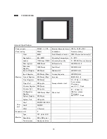
PMIU unit mean TR PMIU0300L/A or TR PMIU0500L/A. The color of case is black. You can connect
Expansion I/O unit to PMIU unit up to 3 (in PMIU0300A) or 5 (in PMIU0500A) units. Expansion I/O
unit cannot use alone, you must use it with PMIU unit. The color of case is red.
Node
The device which it is connected to the COM port, and communicates. For example, if 3 inverters
and 1 touch panel is connected, there is 4 nodes. The table of all nodes is called node list. Refer
4.1.
Project
Minimum unit of files edited with TR PGMS. All data necessary to operate PMIU unit and Expansion
I/O unit (such as unit settings, communication setting, node list, firmware, ladder program, screen
data, etc) are contained.
Key
All TR PMIU unit has 6 Function keys with red LED (Function key LED) in right side of the screen.
You can assign various usage for these keys and LEDs. Refer
9.2.
Object
All things that is put on screen. Some objects can display the data, or can control tags. Such as line,
rectangle, display data, trend graph, etc…
Summary of Contents for TR PMIU
Page 11: ...1 Chapter Chapter Chapter Chapter 1 1 1 1 Introduction Introduction Introduction Introduction ...
Page 15: ...5 Chapter 2 Chapter 2 Chapter 2 Chapter 2 Hardware Hardware Hardware Hardware ...
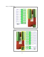
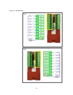
Page 23: ...13 Input Wiring for TR PDIO0808 P Output ...
Page 24: ...14 Wiring for TR PDIO0808 N Input Output ...
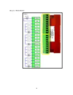
Page 26: ...16 Input Input Wiring for TR PDIX1600 ...
Page 28: ...18 Output Wiring for TRSDOX0016N ...
Page 39: ...29 Chapter Chapter Chapter Chapter 3 3 3 3 TR PGMS TR PGMS TR PGMS TR PGMS ...
Page 83: ...73 Chapter 5 Chapter 5 Chapter 5 Chapter 5 Tag Tag Tag Tag ...
Page 98: ...88 Chapter Chapter Chapter Chapter 6 6 6 6 Task Task Task Task ...
Page 124: ...114 Chapter 8 Chapter 8 Chapter 8 Chapter 8 Screen Screen Screen Screen ...
Page 167: ...157 Note for the numbers of alarm message ...
Page 176: ...166 Appendix Appendix Appendix Appendix ...
Page 181: ...171 ...
Page 182: ...172 ...