


80
5
5
5
5.
.
.
.3
3
3
3
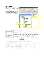
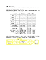
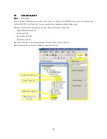
Various tags
Various tags
Various tags
Various tags
5
5
5
5.
.
.
.3
3
3
3.
.
.
.1
1
1
1
System tags
S/SW tags
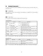
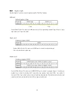
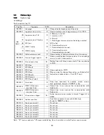
System register tag 1/2
Tag No.
Tag name
R/W
Description
SW 0001
Language
W
Change display language according value
SW 0002
Logger memory status
R
Show percentage use of logger memory (0 to 100%)
_00
Logger memory Full
R
0 : Memory is not full
1 : memory is full
_01
Logger memory Clearing
R
0 : Normal
1 : Data logger memory clear routine being executed.
_02
RTC fail
R
RTC is fail
_14
COM 1 status
R
0 : Communication error
1 : Communication is normal.
SW
0003
_15
COM 2 status
R
0 : Communication error
1 : Communication is normal.
SW 0004
Historical alarm count
R
Shows number of Historical alarms stored in memory.
SW 0005
Screen Trigger register
W
Show current displayed screen number. You can change
screen to write screen number.
SW 0006
Screen saver time
W
Waiting time until Screen saver starts. This can change
in RUN.
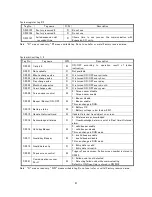
SW 0010
RTC Day
R
SW 0011
RTC Month
R
SW 0012
RTC Year
R
SW 0013
RTC Hour
R
SW 0014
RTC Minute
R
SW 0015
RTC Second
R
SW 0016
RTC Day of week
R
Shows each data of RTC.
When you want to change these value, use Calendar Set
Instruction in ladder block or “Set RTC” task.
SW 0017
Scan time
R
Scan
time
necessary
to
execute
screen,
screen
task/global task. Format is “####.#” m Sec.
SW 0018
COM 1 failed node
reconnect time
R
Shows
time
in
sec
recover
the
communication
with
failed node.
SW 0019
COM 2 failed node
reconnect time
R
Shows
time
in
sec
recover
the
communication
with
failed node.
SW 0023
Popup screen trigger
W
Active popup screen number is stored. Trigger bit is
S0020.
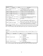
SW 0046
Ladder scan time
Scan time necessary to execute ladder logic.
Format is “####.#” m Sec.
SW 0116
Factory reserved 1
Do not use.
SW 0117
Factory reserved 2
Do not use.
SW 0118
Factory reserved 3
Do not use.
SW 0119
Factory reserved 4
Do not use.
SW 0120
Factory reserved 5
Do not use.
SW 0123
Factory reserved 6
Do not use.
SW 0124
Factory reserved 7
Do not use.
Note : “R” means read only, “W” means writable tag. Do not use (refer or write) Factory reserved area.
Summary of Contents for TR PMIU
Page 11: ...1 Chapter Chapter Chapter Chapter 1 1 1 1 Introduction Introduction Introduction Introduction ...
Page 15: ...5 Chapter 2 Chapter 2 Chapter 2 Chapter 2 Hardware Hardware Hardware Hardware ...
Page 23: ...13 Input Wiring for TR PDIO0808 P Output ...
Page 24: ...14 Wiring for TR PDIO0808 N Input Output ...
Page 26: ...16 Input Input Wiring for TR PDIX1600 ...
Page 28: ...18 Output Wiring for TRSDOX0016N ...
Page 39: ...29 Chapter Chapter Chapter Chapter 3 3 3 3 TR PGMS TR PGMS TR PGMS TR PGMS ...
Page 83: ...73 Chapter 5 Chapter 5 Chapter 5 Chapter 5 Tag Tag Tag Tag ...
Page 98: ...88 Chapter Chapter Chapter Chapter 6 6 6 6 Task Task Task Task ...
Page 124: ...114 Chapter 8 Chapter 8 Chapter 8 Chapter 8 Screen Screen Screen Screen ...
Page 167: ...157 Note for the numbers of alarm message ...
Page 176: ...166 Appendix Appendix Appendix Appendix ...
Page 181: ...171 ...
Page 182: ...172 ...