


150
9
9
9
9.
.
.
.1
1
1
1
USB Host function
USB Host function
USB Host function
USB Host function
9
9
9
9.
.
.
.1
1
1
1.
.
.
.1
1
1
1
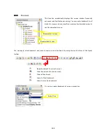
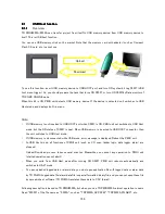
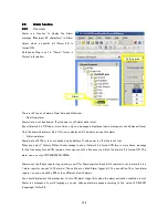
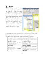
Overview
TR PMIU0300A/0500A can transfer project from itself to USB memory device/from USB memory device to
itself. This is USB host function.
You can use USB memory stick on the market. Note that the memory card with adapter (such as Compact
Flash, SD card, etc.) cannot use.
To use this function, insert USB memory device to USB HOST port, and turn ON system bit tag S0037 (USB
host menu trigger). So, you should prepare the task that turns ON S0037, or turn ON S0037by Data monitor of
TR PGMS ONLINE mode.
When this bit is ON, PMIU unit detects USB memory device. If the device is detected, unit switches to USB
Host mode, and displays built-in menu.
Note
・
If USB memory is not inserted to USB HOST port when S0037 is ON, PMIU unit not switches to USB Host
mode, but the ON status of S0037 is kept. When USB memory is inserted to USB HOST connector, then
the unit switches to USB Host mode.
・
If USB memory is disconnected while USB mode, error message is displayed. Reboot the PMIU unit.
・
In USB Host mode, all functions of PMUI unit (such as I/O scan, ladder logic, data logger, alarm) are
stopped.
・
Upload/Download process takes several minutes. Meanwhile you cannot any operation to PMIU unit
(started operation cannot abort).
・
When you quite from USB Host mode after turning ON S0037, PMIU unit reboots automatically and
switches to HALT mode.
・
To open uploaded logged data or alarm data, you must open application file with logged data or alarm data
by TR PGMS. Logged data file/alarm data file is special formatted binary file, and you cannot open these file
by spread-sheet software (TR PGMS translates these data to CSV format).
Following description is based on TR PMIU0500A, but when you use TR PMIU0300A, almost operation is same.
Read "0500A" of the file name as "0300A", such as “TRP0300A_APP.PZM”, “TRP0300A_FW.ABS”, etc.
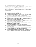
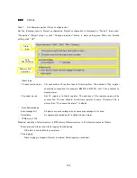
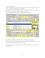
Upload
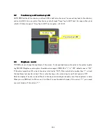
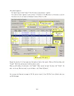
Download
Summary of Contents for TR PMIU
Page 11: ...1 Chapter Chapter Chapter Chapter 1 1 1 1 Introduction Introduction Introduction Introduction ...
Page 15: ...5 Chapter 2 Chapter 2 Chapter 2 Chapter 2 Hardware Hardware Hardware Hardware ...
Page 23: ...13 Input Wiring for TR PDIO0808 P Output ...
Page 24: ...14 Wiring for TR PDIO0808 N Input Output ...
Page 26: ...16 Input Input Wiring for TR PDIX1600 ...
Page 28: ...18 Output Wiring for TRSDOX0016N ...
Page 39: ...29 Chapter Chapter Chapter Chapter 3 3 3 3 TR PGMS TR PGMS TR PGMS TR PGMS ...
Page 83: ...73 Chapter 5 Chapter 5 Chapter 5 Chapter 5 Tag Tag Tag Tag ...
Page 98: ...88 Chapter Chapter Chapter Chapter 6 6 6 6 Task Task Task Task ...
Page 124: ...114 Chapter 8 Chapter 8 Chapter 8 Chapter 8 Screen Screen Screen Screen ...
Page 167: ...157 Note for the numbers of alarm message ...
Page 176: ...166 Appendix Appendix Appendix Appendix ...
Page 181: ...171 ...
Page 182: ...172 ...