2-7
INSTALLATION-SYSTEM DESCRIPTION
SECTION 400-096-202
SEPTEMBER 1992
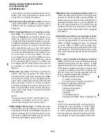
6 PRINTED CIRCUIT BOARD (PCB)
DESCRIPTIONS
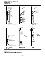
6.00 There have been 15 different types of PCBs
available for use in STRATA DK systems. A maxi-
mum of seven PCBs can be installed in DK24, nine
in DK56, and fifteen in DK96.
6.01 With the exception of the PCTU and PCTUS
PCBs, PCB size and connector provisions are
standardized. All PCBs measure 7.5 x 5.5 inches
(190 x 140 mm). The PCBs connect to the KSU’s
backplane with identical 40-pin male connectors.
Except for the PCTU/PCTUS PCBs, the connec-
tors are positioned in the same location on each
board type.
6.02 PCB external connections are made to the
main distribution frame (MDF) using the following
industry-standard connectors:
•
25-pair Amphenol Female: Twenty-five-pair
amphenol connectors connect digital tele-
CO LINE
TEL LINE
POWER FAILURE TRANSFER
AMPHENOL
CONNECTOR
(J1)
AMPHENOL
CONNECTOR
(J2)
FIGURE 2-8
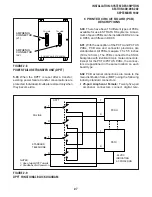
POWER FAILURE TRANSFER UNIT (DPFT)
STANDARD
TELEPHONE
DPFT
PCOU
PSTU
NOTES:
1. One of eight DPFT circuits.
-24 VDC
INDICATING
AC POWER ON
2. Conditions of AC power on.
CO LINE
T
R
T
R
T
R
T
R
FIGURE 2-9
DPFT FUNCTIONAL BLOCK DIAGRAM
5.03 When the DPFT is reset after a transfer,
existing power failure transfer conversations are
protected. Individual circuits are restored only when
they become idle.
Summary of Contents for Strata DK 24
Page 2: ......
Page 10: ......
Page 12: ...INSTALLATION SYSTEM DESCRIPTION SECTION 400 096 202 SEPTEMBER 1992 ...
Page 42: ......
Page 72: ......
Page 102: ......
Page 110: ......
Page 144: ...INSTALLATION TELEPHONE SECTION 400 096 207 SEPTEMBER 1992 ...
Page 164: ......
Page 166: ...INSTALLATION PERIPHERALS SECTION 400 096 208 SEPTEMBER 1992 ...
Page 170: ......
Page 238: ...INSTALLATION WIRING DIAGRAMS SECTION 400 096 209 SEPTEMBER 1992 ...
Page 300: ......
Page 302: ...REMOTE ADMINISTRATION MAINTENANCE PROCEDURES SECTION 400 096 600 SEPTEMBER 1992 ...
Page 372: ......


