8-39
INSTALLATION-PERIPHERALS
SECTION 400-096-208
SEPTEMBER 1992
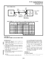
MDF
VOICE MAIL
MACHINE
25-PIN CABLE
(8 CIRCUITS PER PSTU)
(2 CIRCUITS PER PESU)
PSTU/PESU CIRCUIT TIP & RING
(1 PAIR PER PORT)
NOTE:
The CRCU (-4 or -8) must be installed on the
PCTU or PCTUS1 to allow VM DTMF dialing.
PSTU (CKT 1~8)
or
PESU (CKT 1 & 2)
PCTU
or
PCTUS
CRCU (-4 OR -8)
FIGURE 8-26
VOICE MAIL BLOCK DIAGRAM
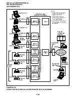
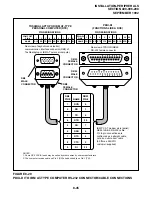
1) Connect the modular cord from the PIOU or
PIOUS TTY port to the PPTC adaptor and
then to the external maintenance modem RS-
232 25-pin connector.
2) Connect the external maintenance modem
line-side to a dedicated CO line (tip and ring)
or to a dedicated PSTU or PESU standard
telephone port (tip and ring). Refer to Wiring
Diagrams, Section 400-096-209, for wiring/
interconnecting details.
3) Set the PIOU or PIOUS SW2 switch to match
the modem or terminal baud rate:
•
Push in for 300 bps (baud rate indicator
CD4/LED is lighted); let out for 1200 bps
(CD4 is not lighted).
4) Set the PIOU or PIOUS SW3 switch to the
TTY position.
NOTE:
The PIOU or PIOUS SW3 switch is set to the
MODEM position for IMDU operation only.
5) Set the P13 jumper plug on the PIOU to the
BELL configuration, or cut the W4 jumper on
the PIOUS (also for BELL configuration).
NOTE:
The P13 (PIOU) or W4 (PIOUS) CCITT con-
figurations are not normally used in the USA.
6) Programming and system testing, via the ex-
ternal maintenance modem, is described in
the Remote Maintenance Procedures, Sec-
tion 400-096-600. Access to the external main-
tenance modem is accomplished as follows:
•
If the modem is connected to a dedicated
CO line, call the CO line number to estab-
lish modem communication.
•
If the modem is connected to a PSTU or
PESU port, call a DK CO line that can be
Summary of Contents for Strata DK 24
Page 2: ......
Page 10: ......
Page 12: ...INSTALLATION SYSTEM DESCRIPTION SECTION 400 096 202 SEPTEMBER 1992 ...
Page 42: ......
Page 72: ......
Page 102: ......
Page 110: ......
Page 144: ...INSTALLATION TELEPHONE SECTION 400 096 207 SEPTEMBER 1992 ...
Page 164: ......
Page 166: ...INSTALLATION PERIPHERALS SECTION 400 096 208 SEPTEMBER 1992 ...
Page 170: ......
Page 238: ...INSTALLATION WIRING DIAGRAMS SECTION 400 096 209 SEPTEMBER 1992 ...
Page 300: ......
Page 302: ...REMOTE ADMINISTRATION MAINTENANCE PROCEDURES SECTION 400 096 600 SEPTEMBER 1992 ...
Page 372: ......


