8-15
INSTALLATION-PERIPHERALS
SECTION 400-096-208
SEPTEMBER 1992
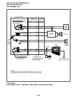
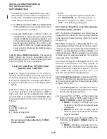
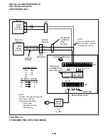
1) Connect PDKU Circuit 5 (T/R and PT/PR) to
the DDCB HKSU modular jack per Chapter 9
DDCB wiring diagram.
2) Connect the door lock wire pair to the DDCB
modular B-jack (pins 3 and 4) per the Chapter
9 diagram.
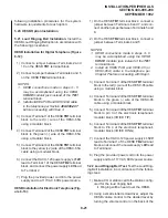
3) On the DDCB, set SW1 to the DOOR position.
4) On the DDCB, set SW2 to the LOCK position.
5) SW3 inside the DDCB can be set to open or
close the door lock relay whenever a door lock
button is pressed: If SW3 is in the "1-2" posi-
tion, the relay will provide a closure when the
button is pressed; if in the "2-3" position, the
door lock relay will open when the door lock
button is pressed.
NOTE:
SW3 comes from the factory in the "1-2"
position.
6) In Program 77-1, set the door lock activation
for three or six seconds and enable the PDKU
ports for DDCB connection.
7) In Program 77-2, enable the DDCB B-jack for
door lock operation.
8) In Program 39, assign door lock
buttons to
stations per the customer’s record sheet.
9) Check each telephone door lock button from
each station: The DDCB modular B-jack (pins
3 and 4) will momentarily open or close (three
or six seconds) when the button is pressed.
NOTE:
The DDCB SW4 strap is not used with STRATA
DK systems. The strap provides an alarm
function with other STRATA systems.
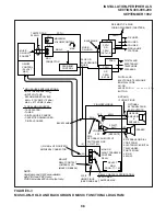
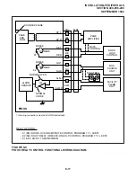
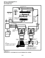
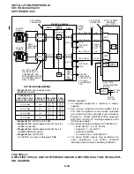
HDCB Installation (Figure 8-11 and Chapter 9
HDCB Wiring Diagram):
1) Cut jumper W9 of the particular PEKU or
PESU that will connect to the HDCB.
2) Connect the Circuit 5 VT/VR and DT/DR pairs
to the HDCB HKSU modular jack per the
Chapter 9 HDCB wiring diagram.
3) Connect the door lock wire pair to the HDCB
modular B-jack (pins 3 and 4) per the Chapter
9 diagram.
4) On the HDCB, set SW1 to the DOOR position.
5) On the HDCB, set SW2 to the LOCK position.
6) W3 inside the HDCB can be set to open or
close the door lock relay whenever a door lock
button is pressed: If W3 is in the "solid-line"
position, the relay will provide a closure when
the button is pressed; if in the "dotted-line"
position, the door lock relay will open when the
door lock button is pressed.
7) In Program 77-1, set the door lock activation
for three or six seconds, and enable the PEKU
and PESU ports for HDCB connection.
8) In Program 77-2, enable the HDCB B-jack for
door lock operation.
9) In Program 39, assign door lock buttons to the
desired stations per the customer’s record
sheet.
10) Check each door lock button from each sta-
tion: The HDCB modular B-jack (pins 3 and 4)
will momentarily close (three or six seconds)
when the appropriate door lock button is
pressed.
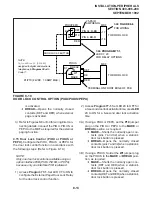
PDKU/PEKU/PESU
Port
No.
DDCB/
HDCB
No.
Program 39 Button
Assignments
First (fifth circuit)
Second (fifth circuit)
Third (fifth circuit)
Fourth (fifth circuit)
04
12
20
28
1
2
3
4
Unlock Door 1
(DRLK 1), Code 72
Unlock Door 2
(DRLK 2), Code 73
Unlock Door 3
(DRLK 3), Code 74
Unlock Door 4
(DRLK 4), Code 75
Summary of Contents for Strata DK 24
Page 2: ......
Page 10: ......
Page 12: ...INSTALLATION SYSTEM DESCRIPTION SECTION 400 096 202 SEPTEMBER 1992 ...
Page 42: ......
Page 72: ......
Page 102: ......
Page 110: ......
Page 144: ...INSTALLATION TELEPHONE SECTION 400 096 207 SEPTEMBER 1992 ...
Page 164: ......
Page 166: ...INSTALLATION PERIPHERALS SECTION 400 096 208 SEPTEMBER 1992 ...
Page 170: ......
Page 238: ...INSTALLATION WIRING DIAGRAMS SECTION 400 096 209 SEPTEMBER 1992 ...
Page 300: ......
Page 302: ...REMOTE ADMINISTRATION MAINTENANCE PROCEDURES SECTION 400 096 600 SEPTEMBER 1992 ...
Page 372: ......

