7-17
INSTALLATION-TELEPHONE
SECTION 400-096-207
SEPTEMBER 1992
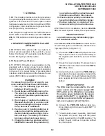
mounting surface and secure with two one-
inch panhead wood screws (Figure 7-17).
3) Attach cover to the metal frame and base.
6.32 Door Phone Volume Control. Adjust the
ring and voice volume to the MDFB in accordance
with the following procedure:
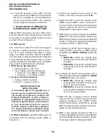
1) Remove the screw from the bottom of the
cover. Detach the cover from the base and
metal frame (Figure 7-17).
2) The volume level is changed by a screw
adjustment on the back of the MDFB. Turn
the screw with a flat-tipped screwdriver while
ringing the MDFB or while on a call with it. The
volume level will change as the screw is
turned.
6.40 Door Phone/Lock Programming Consid-
erations
6.41 The following programs should be consid-
ered when programming the system for door
phones:
Program 03
•
Slots supporting door phones do not require a
special PCB code.
Program 39
•
Assigns door phone and door lock buttons to
electronic and digital telephones.
Program 77-1
•
Assigns DDCBs and HDCBs to ports, door
phone ringing over External Page during the
NIGHT mode, and door lock activation time.
Program 77-2
•
Used to busy out unused MDFB positions and to
identify which DDCBs/HDCBs support the door
lock option, and to set the door phone to ring
one or five times.
Program 79
•
Assigns door phone-to-station ringing assign-
ments.
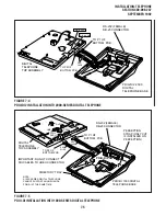
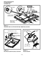
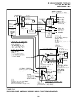
FIGURE 7-17
DOOR PHONE (MDFB) INSTALLATION
KSU
A
B
C
DOOR
PHONE
MOUNTING
SCREWS (4)
EXTERNAL POWER STRAPS
(DDCB ONLY)
NOTE
See Table 9-D regarding external power requirements.
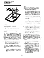
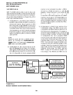
FIGURE 7-16
DOOR PHONE/LOCK CONTROL UNIT
(DDCB/HDCB) INSTALLATION
TWO WALL
MOUNTING
HOLES
DOOR PHONE
BASE
METAL
FRAME
3.25
INCHES
Summary of Contents for Strata DK 24
Page 2: ......
Page 10: ......
Page 12: ...INSTALLATION SYSTEM DESCRIPTION SECTION 400 096 202 SEPTEMBER 1992 ...
Page 42: ......
Page 72: ......
Page 102: ......
Page 110: ......
Page 144: ...INSTALLATION TELEPHONE SECTION 400 096 207 SEPTEMBER 1992 ...
Page 164: ......
Page 166: ...INSTALLATION PERIPHERALS SECTION 400 096 208 SEPTEMBER 1992 ...
Page 170: ......
Page 238: ...INSTALLATION WIRING DIAGRAMS SECTION 400 096 209 SEPTEMBER 1992 ...
Page 300: ......
Page 302: ...REMOTE ADMINISTRATION MAINTENANCE PROCEDURES SECTION 400 096 600 SEPTEMBER 1992 ...
Page 372: ......

