8-3
INSTALLATION-PERIPHERALS
SECTION 400-096-208
SEPTEMBER 1992
J2-26
J2-1
J1-26
J1-1
RELAY
J1-25
J1-50
J1-2
J1-27
J2-2
J2-27
TELEPHONE
CURRENT DETECTOR
TO TEL-T1
TO TEL-R1
TO CO-T1
TO CO-R1
TO PSTU-T1
TO PSTU-R1
TO PCOU-T1
TO PCOU-R1
DG (INPUT)
-24V (INPUT)
PSTU
CONTROL
NOTES:
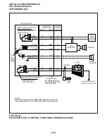
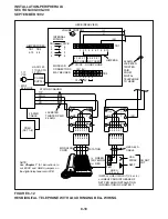
1. Representation of first of eight circuits.
2. Conditions shown with AC power (-24VDC) off.
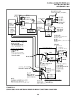
FIGURE 8-2
DPFT CIRCUIT DIAGRAM
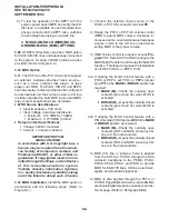
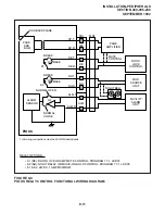
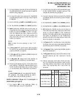
7) Connect the DPFT to the PSTU DG and -24V
terminals (refer to Wiring Diagrams, Section
400-096-209, for PSTU and PCOU wiring/
interconnecting details).
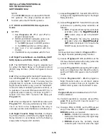
NOTE:
The -24V and DG ground terminals are avail-
able on the PSTU only, not on the PESU.
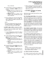
5) Connect the standard telephone stations se-
lected for emergency use to the DPFT J2-
block “TEL-TIP” and “TEL-RING” terminals.
6) Connect the PSTU circuits related to the emer-
gency standard telephones to DPFT
J2-block “PSTU-TIP” and “PSTU-RING”
terminals.
Summary of Contents for Strata DK 24
Page 2: ......
Page 10: ......
Page 12: ...INSTALLATION SYSTEM DESCRIPTION SECTION 400 096 202 SEPTEMBER 1992 ...
Page 42: ......
Page 72: ......
Page 102: ......
Page 110: ......
Page 144: ...INSTALLATION TELEPHONE SECTION 400 096 207 SEPTEMBER 1992 ...
Page 164: ......
Page 166: ...INSTALLATION PERIPHERALS SECTION 400 096 208 SEPTEMBER 1992 ...
Page 170: ......
Page 238: ...INSTALLATION WIRING DIAGRAMS SECTION 400 096 209 SEPTEMBER 1992 ...
Page 300: ......
Page 302: ...REMOTE ADMINISTRATION MAINTENANCE PROCEDURES SECTION 400 096 600 SEPTEMBER 1992 ...
Page 372: ......

