6-5
INSTALLATION-PCB
SECTION 400-096-206
SEPTEMBER 1992
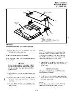
CRCU (-4 or -8)
J4
J3
J1
J2
P2
P3
P8
P9
All PCTU
Types
ROM
(2 each — PCTU4)
(4 each — PCTU 1, 2, 3, and S1)
Located under CRCU
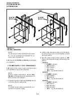
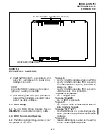
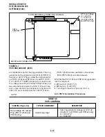
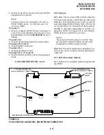
FIGURE 6-3
DTMF RECEIVER UNIT (CRCU) INSTALLATION
3) Apply firm, even pressure to CRCU to ensure
proper mating of connectors.
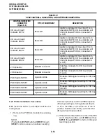
3.20 PCTU Installation Procedures
3.21 Install the PCTU in accordance with the fol-
lowing steps:
CAUTION!
Do not remove plastic insulating shield
from back of PCTU PCB. If the shield comes
off, do not allow the back of the PCB to
contact metal.
1) Remove the PCB from its protective packag-
ing.
2) Set the PCTU P1 switch to the ON position
(PCTU1, 2 only, not on PCTU3, PCTU4, or
PCTUS).
3) Set the PCTU P7 battery strap (BATT) to the
ON position.
NOTE:
The PCTU is shipped from the factory with the
P7 battery strap in the OFF position. Ensure it
is moved to the ON position when installing
the PCTU to protect customer configuration
information stored in the PCTU RAM.
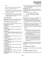
4) Ensure the PCTU has been configured for the
appropriate hardware options (refer to Para-
graph 3.10).
IMPORTANT NOTE:
The power supply must be OFF when in-
stalling the PCTU PCB.
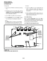
5) Insert the PCTU into Slot 00, labeled PCTU,
and apply firm, even pressure to ensure proper
mating of connectors.
NOTE:
Ensure the component side of the PCTU is
facing right when installing it in the KSU.
Summary of Contents for Strata DK 24
Page 2: ......
Page 10: ......
Page 12: ...INSTALLATION SYSTEM DESCRIPTION SECTION 400 096 202 SEPTEMBER 1992 ...
Page 42: ......
Page 72: ......
Page 102: ......
Page 110: ......
Page 144: ...INSTALLATION TELEPHONE SECTION 400 096 207 SEPTEMBER 1992 ...
Page 164: ......
Page 166: ...INSTALLATION PERIPHERALS SECTION 400 096 208 SEPTEMBER 1992 ...
Page 170: ......
Page 238: ...INSTALLATION WIRING DIAGRAMS SECTION 400 096 209 SEPTEMBER 1992 ...
Page 300: ......
Page 302: ...REMOTE ADMINISTRATION MAINTENANCE PROCEDURES SECTION 400 096 600 SEPTEMBER 1992 ...
Page 372: ......

