8-23
INSTALLATION-PERIPHERALS
SECTION 400-096-208
SEPTEMBER 1992
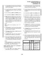
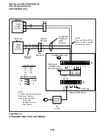
7) Connect the power supply’s +12V lead to
Terminal 1 of the HESB TB2 terminal block,
and connect the OV lead to Terminal 2.
8) Plug the provided power cord into the power
supply and to a 117VAC, 60Hz power source.
9) Set the PIOU or PEPU SW4 switch to the SPO
position.
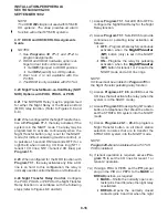
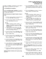
5.24 Amplified Speaker Test. Test the Amplified
Speaker installation in accordance with the follow-
ing steps:
1) Make an external page.
•
The page should be heard over the HESB.
2) Adjust the HESB volume control to the desired
level.
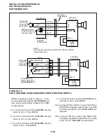
5.25 Talkback Amplified Speaker Installation.
Install the HESB Talkback Amplified Speaker op-
tion in accordance with the following steps (refer to
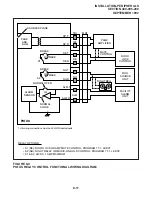
Figure 8-15):
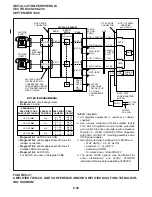
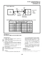
1) Connect a jumper between Terminals 1 and 2
of the HESB TB1 terminal block.
2) Connect a jumper between Terminals 3 and 4
of the HESB TB2 terminal block.
3) Connect a jumper between Terminals 5 and 6
of the HESB TB2 terminal block.
NOTE:
HESB and adjusting the ring volume control
on the telephone.
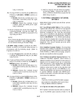
3) If ringing is heard at the station, but not over
the HESB, perform the following check while
the station is ringing:
a) Using a suitable voltmeter, measure volt-
age across Terminals 1 (+) and 2 (-) of
the HESB TB1 terminal block.
•
Voltage indication should be 4.5 ~
5.0VDC.
NOTE:
Ringing stops once the call is manually an-
swered. There should be NO voltage potential
across Terminals 1 and 2.
b) If voltage is not as specified during ring-
ing, check that the telephone wiring
connections to the HESB have been
made properly (wires to Terminals 1 and
2 of the HESB TB1 terminal block may
have been reversed).
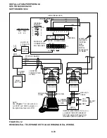
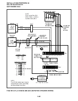
5.23 Amplified Speaker Installation. Install the
HESB Amplified Speaker option in accordance
with the following steps (refer to Figure 8-14):
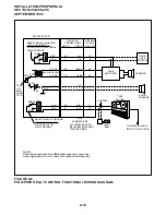
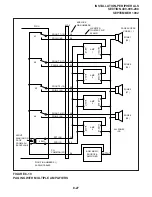
1) Connect a jumper between Terminals 1 and 2
of the HESB TB1 terminal block.
2) Connect a jumper between Terminals 6 and 7
of the HESB TB1 terminal block.
3) Connect a jumper between Terminals 5 and 8
of the HESB TB1 terminal block.
4) Connect a jumper between Terminals 3 and 4
of the HESB TB2 terminal block.
5) Connect a jumper between Terminals 5 and 6
of the HESB TB2 terminal block.
6A) If using a PIOU or PEPU, connect the PIOU or
PEPU 600-ohm page output (Pins 13 and 38)
to Terminals 3 and 4 of the HESB TB1 termi-
nal block.
6B) If using a PIOUS, connect the PIOUS 600-
ohm page output (SPT and SPR) to Terminals
3 and 4 of the HESB TB1 terminal block.
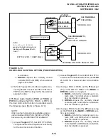
FIGURE 8-16—HESB WALL MOUNTING
ONE WALL
MOUNTING
HOLE
Summary of Contents for Strata DK 24
Page 2: ......
Page 10: ......
Page 12: ...INSTALLATION SYSTEM DESCRIPTION SECTION 400 096 202 SEPTEMBER 1992 ...
Page 42: ......
Page 72: ......
Page 102: ......
Page 110: ......
Page 144: ...INSTALLATION TELEPHONE SECTION 400 096 207 SEPTEMBER 1992 ...
Page 164: ......
Page 166: ...INSTALLATION PERIPHERALS SECTION 400 096 208 SEPTEMBER 1992 ...
Page 170: ......
Page 238: ...INSTALLATION WIRING DIAGRAMS SECTION 400 096 209 SEPTEMBER 1992 ...
Page 300: ......
Page 302: ...REMOTE ADMINISTRATION MAINTENANCE PROCEDURES SECTION 400 096 600 SEPTEMBER 1992 ...
Page 372: ......


