


5-1
INSTALLATION-KSU
SECTION 400-096-205
SEPTEMBER 1992
1 GENERAL
1.00 This chapter provides the procedures neces-
sary to install the DK key service units (KSUs).
Included in the chapter are mounting consider-
ations, grounding instructions, and instructions to
test the power supply. Instructions to remove and
replace the power supply are also provided.
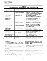
2 KSU INSTALLATION
2.00 The KSU may be either wall-mounted or
tabletop mounted. The following paragraphs pro-
vide procedures for both mounting options.
2.01 To optimize airflow and ventilation:
•
Ensure that the installation site provides the
minimum clearances specified in Installation
Site Requirements, Section 400-096-203, Para-
graph 3.
•
Do not block the ventilation holes at the rear
and both sides of the KSU.
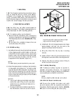
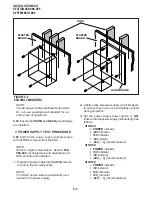
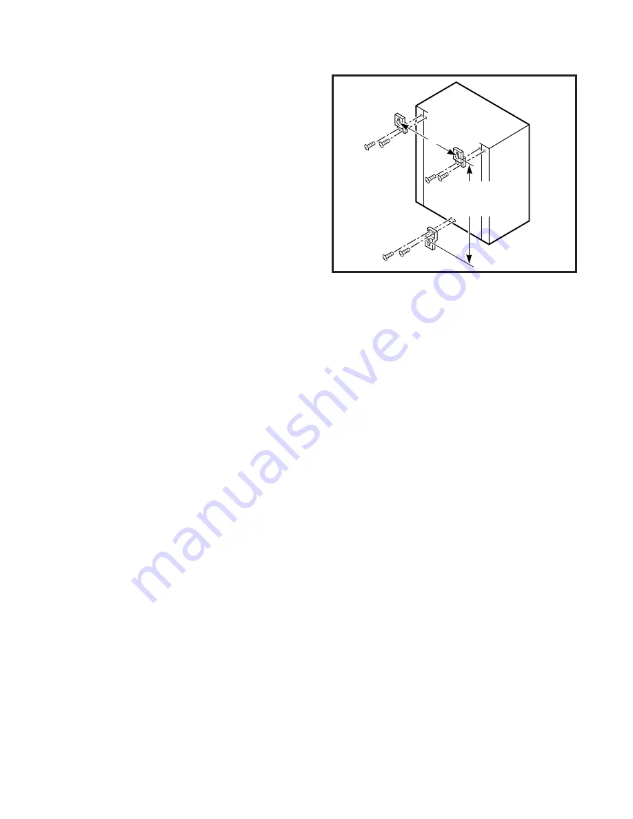
2.10 Wall Mounting
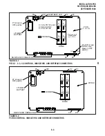
1) Install the three wall-mounting brackets (packed
in the shipping carton with the KSU) on the rear
of the KSU in both upper corners, and at the
bottom center. Secure each bracket to the KSU
with the back panel screws and the screws
supplied with the brackets (Figure 5-1).
NOTE:
The KSU back panel should not be removed.
2) Mark the appropriate mounting screw locations
on the wall by using Figure 5-1, or hold the KSU
against the wall at the selected mounting loca-
tion. Mark the positions of the holes in the flat
part of each mounting bracket where they con-
tact the wall. Mounting screws will be installed
at these locations.
NOTES :
1. The screw locations should align with studs
behind the wall. If they do not, use either
wall anchors or a hard board between the
wall and the KSU.
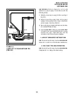
2. If using a hard board, install screws first to
the hard board, and then secure the hard
15.9 in. (DK96)
12.4 in. (DK56)
12.6 in. (DK24)
19.2 in. (DK96)
16.3 in. (DK56)
11.3 in. (DK24)
FIGURE 5-1
WALL MOUNTING BRACKET INSTALLATION
board to the wall, making sure the screws
align with the studs (Figure 5-2).
3) Install two 1.25-inch long panhead wood screws
approximately half way into the wall at the
upper mounting bracket locations.
4) Hang the KSU from the top two mounting
screws.
5) Install a third 1.25-inch panhead wood screw
through the hole in the bottom mounting bracket.
6) Tighten the three mounting screws firmly to
secure the KSU to the wall.
2.20 Tabletop Mounting
2.21 Tabletop mounting requires no special in-
stallation procedures. However, it is suggested
that the top wall-mounting brackets be installed to
ensure adequate ventilation at all times.
NOTE:
Do not install the KSU directly on the floor.
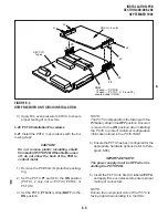
2.30 KSU AC Power and Ground
2.31 Ensure the system AC power and earth
ground complies with the requirements listed in
Installation Site Requirements, Section 400-096-
203, prior to connecting the AC power plug.
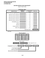
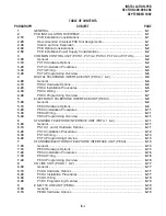
Summary of Contents for Strata DK 24
Page 2: ......
Page 10: ......
Page 12: ...INSTALLATION SYSTEM DESCRIPTION SECTION 400 096 202 SEPTEMBER 1992 ...
Page 42: ......
Page 72: ......
Page 102: ......
Page 110: ......
Page 144: ...INSTALLATION TELEPHONE SECTION 400 096 207 SEPTEMBER 1992 ...
Page 164: ......
Page 166: ...INSTALLATION PERIPHERALS SECTION 400 096 208 SEPTEMBER 1992 ...
Page 170: ......
Page 238: ...INSTALLATION WIRING DIAGRAMS SECTION 400 096 209 SEPTEMBER 1992 ...
Page 300: ......
Page 302: ...REMOTE ADMINISTRATION MAINTENANCE PROCEDURES SECTION 400 096 600 SEPTEMBER 1992 ...
Page 372: ......


