


6-28
INSTALLATION-PCB
SECTION 400-096-206
SEPTEMBER 1992
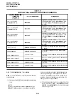
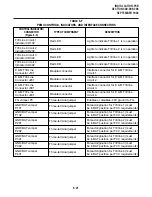
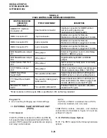
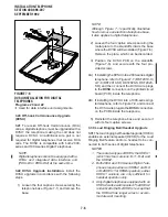
TABLE 6-I
PEPU CONTROLS AND INTERFACE CONNECTORS
CONTROL/INDICATOR/
CONNECTOR
(Figure 6-13)
TYPE OF COMPONENT
DESCRIPTION
M/B Make/Break
Jumper Plug P10
Three-terminal jumper plug
External Page/Door Lock Control Relay
MAKE or BREAK jumper plug.
M/B Make/Break
Jumper Plug P11
Three-terminal jumper plug
Night/Hold Relay MAKE or BREAK jumper
plug.
SPI/SPO Internal/External
Amplifier Switch
SW4
Two-position slide switch
Selects built-in 3-watt amplifier or
600-ohm output for External Page/BGM
operation.
Volume Control
VR1
Trim potentiometer
Adjusts volume of built-in 3-watt amplifier.
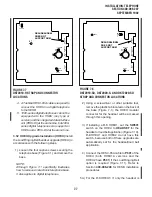
appropriate hardware options. (Refer to Para-
graph 11.10 and Section 400-096-208.)
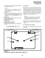
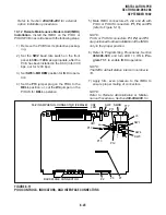
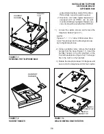
NOTE:
Ensure the PEPU’s component side is facing
right when installing it in the KSU.
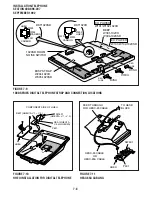
3) Insert the PEPU into the last slot (Slot 06 of
DK24, Slot 08 for DK56, and Slot 14 for DK96),
and apply firm, even pressure to ensure proper
mating of connectors.
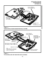
4) After installing the PEPU, gently pull the PCB
outward. If the connectors are properly mated,
a slight resistance will be felt.
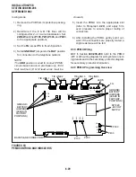
11.30 PEPU Wiring
11.31 Refer to Peripheral Equipment Installation,
Section 400-096-208, for external option installa-
tion; see Wiring Diagrams, Section 400-096-209,
for wiring/interconnecting details.
11.40 PEPU Programming Overview
11.41 The following programming parameters may
be specified for the PEPU:
Program 03
•
Specify Code 41 for the slot that will support a
PEPU.
Program 10-2
•
Use to activate External Page with All Call Page
(with access code 39 only, not with All Call Page
button).
Program 77-1
•
Use to assign relay control options.
Program 78
•
Use to set Night Ringing over External Page.
Summary of Contents for Strata DK 24
Page 2: ......
Page 10: ......
Page 12: ...INSTALLATION SYSTEM DESCRIPTION SECTION 400 096 202 SEPTEMBER 1992 ...
Page 42: ......
Page 72: ......
Page 102: ......
Page 110: ......
Page 144: ...INSTALLATION TELEPHONE SECTION 400 096 207 SEPTEMBER 1992 ...
Page 164: ......
Page 166: ...INSTALLATION PERIPHERALS SECTION 400 096 208 SEPTEMBER 1992 ...
Page 170: ......
Page 238: ...INSTALLATION WIRING DIAGRAMS SECTION 400 096 209 SEPTEMBER 1992 ...
Page 300: ......
Page 302: ...REMOTE ADMINISTRATION MAINTENANCE PROCEDURES SECTION 400 096 600 SEPTEMBER 1992 ...
Page 372: ......


