


9-2
INSTALLATION-WIRING DIAGRAMS
SECTION 400-096-209
SEPTEMBER 1992
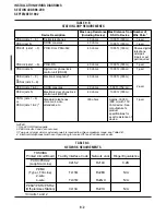
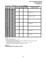
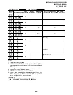
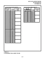
TABLE 9-B
STATION LOOP REQUIREMENTS
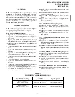
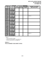
TABLE 9-C
NETWORK REQUIREMENTS
TOSHIBA
Printed Circuit Board
PCOU/PCOU2
(Loop Start Line)
PEMU
(Type l, TIE Line)
2-wire
4-wire
PESU*/PSTU/PSTU2
(Off-premises Station)
Facility Interface Code
02LS2
TL11M
TL31M
0L13A
Network Jack
RJ14C
RJ2EX
RJ2GX
RJ21X
Ringer Equivalence
0.2B
N/A
N/A
N/A
*
Circuits 1 and 2
NOTES:
1. Use 24 AWG twisted pairs.
2. PESU circuits 3 and 4 are not used.
3. Two-pair or larger wire (or external power) is required to achieve maximum range, see Table 9-D.
4. Electronic telephones must have 3-pair wiring to receive Off-hook Call Announce calls.
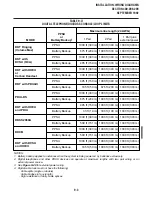
Device Description
Max Loop Resistance
(Including Device)
Max Distance from
KSU to Device
Number of
Wire Pairs
1
Digital telephones
DDSS consoles
PSTU (ckts 1 ~ 8)
or
PESU (ckts 1 & 2)
2
PDKU (ckts 1 ~ 8)
PDKU (ckt 8)
1000 ft. (303 m)
1000 ft. (303 m)
1-pair
1-pair
PDIU-DI or PDIU-DI2
PDKU1 (ckts 1 ~ 7)
1000 ft. (303 m)
Shares digital
telephone
wire-pair.
2-pair or ext
pwr required
PDIU-DS
1000 ft. (303 m)
1-pair
PDKU2 (ckts 1 ~ 8)
1-pair
Approx. 3000 ft.
(909 m) with 150
ohm device. See
manufacturer's
product
specifications for
exact resistance of
device.
300 ohms
PDKU (ckts 5)
40 ohms
1000 ft. (303 m)
1-pair
HDSS consoles
PEKU (ckts 7 & 8)
500 ft. (152 m)
20 ohms
2-pair
Standard telephones,
voice mail, auto
attendant, etc.
PEKU (ckts 5)
1000 ft. (303 m)
40 ohms
Electronic door phone/lock
control unit (HDCB)
PEKU (ckts 1 ~ 8)
or
PESU
2
(ckts 5 ~ 8)
1000 ft. (303 m)
40 ohms
Electronic telephone
4
Digital door phone/lock
control unit (DDCB)
40 ohms
40 ohms
40 ohms
40 ohms
Summary of Contents for Strata DK 24
Page 2: ......
Page 10: ......
Page 12: ...INSTALLATION SYSTEM DESCRIPTION SECTION 400 096 202 SEPTEMBER 1992 ...
Page 42: ......
Page 72: ......
Page 102: ......
Page 110: ......
Page 144: ...INSTALLATION TELEPHONE SECTION 400 096 207 SEPTEMBER 1992 ...
Page 164: ......
Page 166: ...INSTALLATION PERIPHERALS SECTION 400 096 208 SEPTEMBER 1992 ...
Page 170: ......
Page 238: ...INSTALLATION WIRING DIAGRAMS SECTION 400 096 209 SEPTEMBER 1992 ...
Page 300: ......
Page 302: ...REMOTE ADMINISTRATION MAINTENANCE PROCEDURES SECTION 400 096 600 SEPTEMBER 1992 ...
Page 372: ......


