Maintenance and Troubleshooting
Opto22 Problems
Thermo Fisher Scientific
Micro-Tech 9101/9201 Reference Manual, Rev J
4-17
Here is the procedure to follow to test the Opto22 input module.
1.
Follow steps 1–2 in the “Navigating to the Test Output Screen”
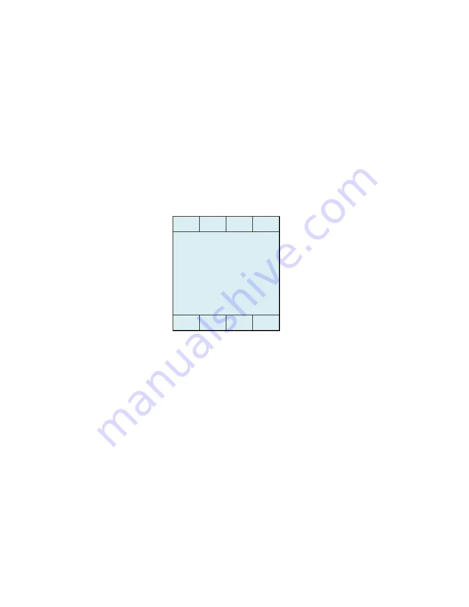
section to display the “Digital Input Test” screen shown below.
The screen indicates input status—that is, 0 = open, 1= closed. The
display reads right to left, that is from Inputs 1 through to Input 5. If
your Micro-Tech is equipped with an optional digital input/output board,
press the Next button to display Inputs 6–21. In addition, note that
Inputs 1 and 2 are reserved for the speed input.
2.
Voltage input. Measure source voltage input.
If GOOD—Proceed to “View Opto LED” (see step 3).
If BAD—Apply appropriate voltage to input terminals.
Test Procedure
for the Input
Module
BATCH
-TEST SCROLL 3 -
Dig input test
Slot #0 00111
READY
ALARM
CALIB
NEXT
Summary of Contents for Micro-Tech 9101
Page 1: ...Micro Tech 9101 9201 Integrator Reference Manual REC 4281 Rev J Part Number 127336 English...
Page 82: ......
Page 118: ......
Page 124: ...A 2 Micro Tech 9101 9201 Reference Manual Rev J Thermo Fisher Scientific...
Page 172: ......
Page 234: ......
Page 315: ......
Page 316: ......
Page 317: ......
Page 318: ......
Page 319: ......
Page 320: ......
Page 321: ......
Page 322: ......
Page 323: ......
Page 324: ......
Page 325: ......
Page 326: ......
Page 327: ......
Page 328: ......
Page 329: ......


