background image

5

  Ion Source and Inlet Valve

Ion Source

Thermo Scientific

DSQ II Hardware Manual

173

Lenses

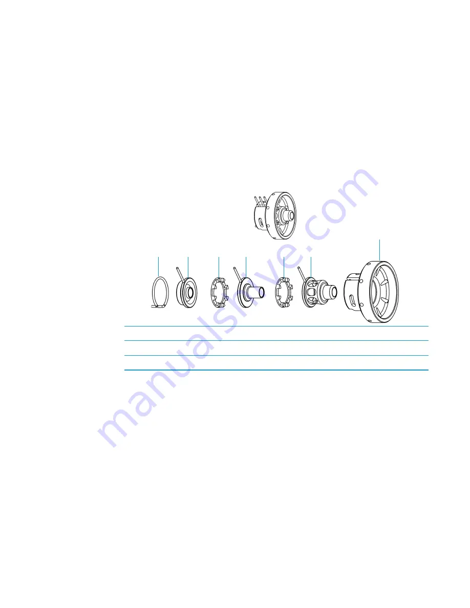
Lenses transmit the ions formed in the ion volume to the prefilter. The lenses are stainless steel 
plates and tubes to which voltages are applied. The three lenses are designated L1, L2, and L3, 
with L1 being nearest to the ion volume. 

A lens’ electrical connection is made through a stainless steel pin protruding from the edge of 
the lens. A small 3-pin lens connector attaches to these pins and carries the voltage from the 
electrical feedthrough to the lens. 

Figure 90. 

Ion Source Lenses

1

Lens Clip

4

Lens 2

2

Lens  1

5

Lens  3

3

Two Lens Spacers

6

Lens Holder

 1

 2

 3

 4

 3

 5

 6

Summary of Contents for DSQ II

Page 1: ...DSQ II Hardware Manual 120299 0002 Revision C December 1 2009 ...

Page 2: ...nd service contract coverage Thermo Fisher Scientific Inc provides this document to its customers with a product purchase to use in the product operation This document is copyright protected and any reproduction of the whole or any part of this document is strictly prohibited except with the written authorization of Thermo Fisher Scientific Inc The contents of this document are subject to change w...

Page 3: ... and technical reports Name __________________________________________________Title__________________________________________________________________ Company __________________________________________________ __________________________________________________________________ Address ___________________________________________________ ________________________________________________________________...

Page 4: ......

Page 5: ... standards Changes to your system include replacing a part or adding components options or peripherals not specifically authorized and qualified by Thermo Fisher Scientific To ensure continued compliance with EMC and safety standards replacement parts and additional components options and peripherals must be ordered from Thermo Fisher Scientific or one of its authorized representatives FCC Complia...

Page 6: ...missions Your instrument is designed to work in a controlled electromagnetic environment Do not use radio frequency transmitters such as mobile phones in close proximity to the instrument For manufacturing location see the label on the instrument WEEE Compliance This product is required to comply with the European Union s Waste Electrical Electronic Equipment WEEE Directive 2002 96 EC It is marked...

Page 7: ...ere Hinweise die nützlich sind um die Produkte zu identifizieren die unter diese RoHS Anweisung fallen finden sie unter www thermo com WEEERoHS Conformité DEEE Ce produit doit être conforme à la directive européenne 2002 96 EC des Déchets d Equipements Electriques et Electroniques DEEE Il est marqué par le symbole suivant Thermo Fisher Scientific s est associé avec une ou plusieurs compagnies de r...

Page 8: ......

Page 9: ...reparing the DSQ II for Maintenance 25 Removing the Front and Top Covers 25 Removing the Right Cover 27 Removing the Left Cover 29 Removing the Vacuum Manifold Cover 32 Cleaning Stainless Steel Components 34 Cleaning Non Stainless Steel or Hybrid Components 36 Cleaning the Ion Source Components 38 Cleaning the Ion Volume with an Inlet Valve 38 Cleaning the Ion Volume Without an Inlet Valve 43 Clea...

Page 10: ...Electrometer Board 89 Replacing the Foreline Pressure Gauge and Foreline Adapter 91 Replacing the Inlet Valve Seal 93 Replacing the Ion Gauge Optional Upgrade 94 Replacing the Lens Interface Board 96 Replacing the Low Pass Filter Board 98 Replacing the Power Module 101 Replacing the Power Module Fuses 103 Replacing the Rear Cooling Fans 104 Replacing the RF Detector Board 107 Replacing the RF Gene...

Page 11: ...grade 158 Rotary Vane Pump 159 Vacuum Manifold 160 Gas Inlet Components 162 Calibration Gas Flow Module 163 CI Reagent Gas Flow Module Upgrade 164 Vent Valve Solenoid 165 Chapter 5 Ion Source and Inlet Valve 167 Ion Source 167 Filament 169 Ion Source 170 Ion Volume 172 Lenses 173 Magnets and Magnet Yoke 174 Inlet Valve Upgrade 175 Ball Valve 177 Inlet Valve Lever 178 Guide Bar Housing 179 I R Tool...

Page 12: ...le Parts List 198 Gas Inlets and Gauges Parts List 199 Boards and Cables Parts List 201 Turbomolecular Pump Parts List 208 Split Flow Turbomolecular Pump Upgrade Parts List 210 Inlet Valve Upgrade Parts List 212 Power Module Parts List 214 Installation Kit Parts List 214 Documentation Parts List 215 Miscellaneous Items Parts List 216 Electronic Assemblies 218 Power Distribution 219 Remote Start Ca...

Page 13: ...fication of the individual compounds present in the sample IMPORTANT Thermo Fisher Scientific systems are designed to optimize both the separation and detection capabilities of GC MS techniques and combine them in a synergistic fashion to provide high performance analytical capabilities for both research and routine applications More information on the use of this system can be found in related do...

Page 14: ...autionary message When you see a safety alert on your instrument or in the publications please carefully follow the safety instructions before proceeding CAUTION This is the safety alert word to prevent actions that may cause personal injury or instrument damage We use it to highlight information necessary to prevent personal injury or damage to software loss of data or invalid test results or mig...

Page 15: ...CHEMICAL HAZARD This symbol indicates that chemical damage or physical injury could or may occur INSTRUMENT DAMAGE This symbol indicates that damage to the instrument or module may occur This damage may not be covered under the standard warranty LIFTING HAZARD This symbol indicates two or more people are required to lift the object to prevent a physical injury that could or may occur MATERIAL AND ...

Page 16: ...n thermofisher com Related Documentation In addition to this guide Thermo Scientific provides the following documents for the DSQ II These documents are also available on a Print By Request basis DSQ II Document Set PN 120299 DSQ II Preinstallation Guide PN 120299 0001 DSQ II Hardware Manual PN 120299 0002 DSQ II User s Guide PN 120299 0003 Instrument Help is available from within the Tune softwar...

Page 17: ...his chapter describes basic operations of the TRACE GC Ultra and DSQ II Contents Installing a Column into the GC MS System on page 4 Removing a Column from the GC MS System on page 15 Starting Up the GC MS System on page 17 Shutting Down the GC MS System on page 18 ...

Page 18: ...15 m 0 25 mm i d 0 25 μm PN 76317 3015 CI Ion Volume PN 119650 0230 if applicable Column measuring tool PN 119640 0550 Copper tubing clean PN 76381 0041 1 8 in o d 0 030 in wall Digital voltmeter Fluke model 77 or equivalent Dusting spray containing tetrafluoroethane Falcon Dust Off MicroCare MicroBlast or equivalent Flashlight small hand held Flow meter Thermo Scientific GFM Pro PN 66002 010 Forc...

Page 19: ... Phillips 2 Syringe 10 μL 70 mm needle PN 3650 0103 Tape measure Teflon thread tape Tissue lint free Tubing cutter Test mix octafluoronaphthalene and benzophenone PN 120150 TEST Transfer line ferrule 0 4 mm i d PN A0101 18100 Wrench adjustable 12 in Wrench Allen 1 16 in Wrench set Allen 5 2 2 5 3 4 5 mm PN 3812 0100 Wrench set open ended 5 17 mm Wrench set open ended 1 4 in 5 16 in 7 16 in 2 9 16 ...

Page 20: ...66002 001 or equivalent Flowmeter Thermo Scientific GFM Pro flowmeter PN 66002 010 or equivalent Tissue lint free Transfer line ferrule 0 4 mm i d Wrench open ended 5 16 in Wrench open ended 6 mm Wrenches two open ended 7 16 in For information about setting up the TRACE GC Ultra or FOCUS GC refer to the documentation supplied with the instrument 1 Connect the column to the injector that is inside ...

Page 21: ...additional quarter turn with the wrench h Use a scoring wafer to score and break the column outlet about 2 5 cm 1 in from the end i Power on the TRACE GC Ultra 2 Set up the TRACE GC Ultra a Set the oven and injector temperatures to 30 C b Set the injector flow to 1 0 mL min c Turn off vacuum compensation under the Right or Left Carrier menu d Dip the column outlet in a small vial of methanol Bubbl...

Page 22: ...and press Enter The following menu appears if you select the left column and and use the settings below to set the physical characteristics of the column Note The available options Right column or Left column will differ depending on the configuration of your GC COLUMN INFORMATION Right column Left column Note Make sure the Vacuum Compensation parameter is set to OFF in the Carrier menu which is a...

Page 23: ...olumn scroll to Run column eval and press ENTER The system will set the Column K factor by pressurizing the column to obtain a nominal carrier flow of 5 mL min The display shows the pressure i Using the flowmeter measure the carrier gas flow at the outlet of the column Scroll to Measured Flow and set the value of the flow j The following message will display if the operation was successful Pre pos...

Page 24: ...icate a blockage 4 Perform a column leak check a Carefully push the capillary column end into the column section of the column flow meter connector as shown in Figure 3 Figure 3 Leak Check b Press Leak Check to access the Leak Check Columns menu c Scroll to a channel to open the left or right column s leak check menu CAUTION INSTRUMENT DAMAGE Do not allow the clear plastic component to exceed 80 C...

Page 25: ...closed and the channel is pressurized with carrier gas to the leak check set point i The system monitors the pressure for one minute If the pressure does not drop more than the maximum allowed sensitivity value then the leak check will pass If the leak check did not pass you should use the leak detector to find and fix the leaks j Repeat the column evaluation and leak check until no leaks are indi...

Page 26: ...low it to cool before continuing c Unwind about one turn of the column from the column outlet end d Wipe about 300 mm 12 in of the column with a tissue soaked in methanol e Insert the column through the septa transfer line nut and ferrule Wipe the column again with a tissue soaked in methanol f Use a scoring wafer to score and break the end of the column Use a magnifying glass to check for an even...

Page 27: ...e column back so that it is flush with the end of the column measuring tool Tighten the transfer line nut 4 Slide the septum up to the back of the transfer line nut 5 Remove the column transfer line nut and ferrule from the column measuring tool Tip Slide a septum on the column before adding the transfer line nut to make it easier to measure the proper distance between the nut and the end of the c...

Page 28: ...he maximum temperature you will operate the column normally 300 C b Wait 10 minutes c Lower the oven temperature to 30 C and allow it to cool before continuing d Re tighten the transfer line nut and the transfer line union 9 Set up the TRACE GC Ultra a Make sure the column does not have any sharp bends and that it does not touch any metal objects or walls inside the oven b Raise the oven temperatu...

Page 29: ...ing the Ion Volume Without an Inlet Valve on page 43 8 Condition the transfer line ferrule Graphite vespel ferrules like the transfer line ferrule require conditioning to ensure a leak tight seal a Raise the oven temperature to the maximum temperature you will operate the column normally 300 C b Wait 10 minutes c Lower the oven temperature to 30 C and allow it to cool before continuing d Re tighte...

Page 30: ...8 Reattach the DSQ II front and top covers 9 Condition the transfer line ferrule Graphite vespel ferrules like the transfer line ferrule require conditioning to ensure a leak tight seal a Raise the oven temperature to the maximum temperature you will operate the column normally 300 C b Wait 10 minutes c Lower the oven temperature to 30 C and allow it to cool before continuing d Re tighten the tran...

Page 31: ... see Shutting Down the GC MS System on page 18 Lower the oven injector and transfer line temperatures to 30 C and allow them to cool before continuing b Once the DSQ II is cooled down power off the TRACE GC Ultra 2 Remove the column from the transfer line a Unscrew the transfer line nut b Remove the column from the transfer line Figure 6 Transfer Line Components WARNING BURN HAZARD The oven inject...

Page 32: ...are Manual Thermo Scientific 3 Remove the column from the injector a Unscrew the injector nut b Remove the column from the injector Figure 7 TRACE GC ULtra Injector Components 1 Injector 4 Column 2 Injector Ferrule 5 Column Outlet 3 Injector Nut 6 Transfer Line 1 4 3 4 2 6 5 ...

Page 33: ...er operating pressure and the turbomolecular pump to power on b Set the transfer line to the desired operating temperature normally 250 C by selecting Aux Temp Enter on the TRACE GC Ultra Enter the temperature 3 Open Xcalibur on the computer a Check the heater status by clicking the Heaters tab in the DSQ II Status pane If the ion source is not set to the right temperature normally 200 C change it...

Page 34: ...e window b Select Instrument Shutdown to begin the automatic shutdown process which includes Displaying the Xcalibur Shut Down window Turning off the calibration and CI reagent gas Turning off the voltages to the ion source quadrupole and ion detector Turning off the ion source heater Turning off the turbomolecular pump Xcalibur counting down ten minutes for the pump to slow down Xcalibur waiting ...

Page 35: ...om the wall socket 4 Wait for the TRACE GC Ultra oven injector and transfer line to cool to room temperature 5 Power off all the remaining instruments a Power off the TRACE GC Ultra by switching the main circuit breaker to OFF 0 b Turn off the GC s helium supply at the tank c Power off the autosampler optional by switching the main power switch to OFF IMPORTANT The process ends here if you are pla...

Page 36: ...1 Basic Operations Shutting Down the GC MS System 20 DSQ II Hardware Manual Thermo Scientific ...

Page 37: ... the instrument Contents Components That Require Maintenance on page 22 List of Tools on page 22 Recommended Maintenance Schedule on page 23 Running Benchmark Tests on page 24 Preparing the DSQ II for Maintenance on page 25 Cleaning the Ion Source Components on page 38 Replacing the Electron Multiplier on page 59 Maintaining the Turbomolecular Pump on page 62 Maintaining the Rotary Vane Pump on pa...

Page 38: ...ents in the DSQ II that do not require maintenance but may need to be replaced in the event that there is a problem with the instrument These components are described in Maintaining Components Outside the Vacuum Manifold on page 70 List of Tools To perform maintenance on a DSQ II system you will need the following tools Gas clean and dry Gloves clean lint and powder free Gloves latex impermeable L...

Page 39: ...e 38 which may include Cleaning the Ion Volume with an Inlet Valve see page 38 Cleaning the Ion Volume Without an Inlet Valve see page 43 Cleaning the Ion Source Lenses and Prefilter see page 45 Replacing the Ion Source Filament see page 53 Replacing the Electron Multiplier see page 59 which may include Maintaining the Turbomolecular Pump see page 62 Maintaining the Rotary Vane Pump see page 62 wh...

Page 40: ...r benchmark test results 4 Run the benchmark test again and compare the results 5 If the DSQ II is still not operating at optimal performance clean the lenses ion source assembly and prefilter The frequency in which you clean the DSQ II depends on the types and amounts of samples and solvents you introduce into the instrument In general the closer a component is to the sample introduction point th...

Page 41: ...overs overlap so they must be removed in the order of front top right and left as you face the front of the instrument Removing the Front and Top Covers To remove the front and top covers you will need a Phillips 2 screwdriver 1 Cover the work area with a lint free cloth Figure 10 Components Accessed by Removing the Top and Front Covers 1 Power Module 3 Calibration Gas Flow Module 2 CI Reagent Gas...

Page 42: ...nt cover 4 Loosen the fastener located on the front of the DSQ II that attaches the top cover to the chassis Figure 11 Removing the Top Cover Fastener 5 Slide the top cover forward about 2 5 cm 1 inch 6 Lift the top cover up and away from the DSQ II 7 Reverse these steps to reinstall the top cover WARNING ELECTRICAL SHOCK HAZARD Before proceeding unplug the DSQ II to avoid an electrical shock Top ...

Page 43: ...t down and vent the DSQ II as described in Shutting Down the GC MS System on page 18 3 Remove the front and top covers as described in Removing the Front and Top Covers on page 25 4 Remove the capillary column as described in Preparing the DSQ II for Maintenance on page 25 1 Inlet Valve 4 High Vacuum Pump 2 Lens Interface Board 5 Fore Pressure Gauge and Foreline Adapter 3 Transfer Line 6 Turbomole...

Page 44: ...mo Scientific 5 Remove the two screws connecting the right cover to the chassis Figure 13 Removing the Screws Holding the Right Cover in Place 6 Slide the cover towards the back of the instrument and pull it away 7 Reverse these steps to reinstall the right cover Screws holding the right cover ...

Page 45: ...ver 1 Cover the work area with a lint free cloth Figure 14 Components Accessed by Removing the Left Cover 1 CI Reagent Gas Flow Module optional 6 Vacuum Control Board 2 Calibration Gas Flow Module 7 DC Driver 3 Electrometer Board 8 Vent Valve Solenoid 4 RF Detector Board 9 Conversion Dynode Electron Multiplier Power Supply 5 Low Pass Filter Board 10 RF Generator Board 2 3 4 5 6 7 8 9 1 10 ...

Page 46: ...he DSQ II as described in Shutting Down the GC MS System on page 18 3 Remove the front and top covers as described in Removing the Front and Top Covers on page 25 4 Remove the screw located on the back of the instrument that connects the left cover to the chassis 1 Digital Board 2 Analog Board 2 1 WARNING ELECTRICAL SHOCK HAZARD Before proceeding unplug the DSQ II to avoid an electrical shock ...

Page 47: ...n pull the cover away 6 Reverse these steps to reinstall the left cover REV HIGH VOLTAGE AND HOT SURFACES WARNING CAUTION Screw holding left cover in place WARNING INSTRUMENT DAMAGE The analog and digital boards are attached to interior side of the left cover so that cover is significantly heavier than the right cover Do not pull the cover too far away from the instrument when you open it or you c...

Page 48: ...the work area with a lint free cloth Figure 17 Components Accessed By Removing the Vacuum Manifold Cover 2 Shut down and vent the DSQ II as described in Preparing the DSQ II for Maintenance on page 25 CAUTION INSTRUMENT DAMAGE Keep the vacuum manifold cover attached to the instrument while performing maintenance Even small amounts of dust on the electron multiplier conversion dynode or quadrupole ...

Page 49: ... lint free cloth if necessary 6 Perform maintenance on the components of the vacuum manifold Cleaning the Ion Volume with an Inlet Valve on page 38 or Cleaning the Ion Volume Without an Inlet Valve on page 43 Cleaning the Ion Source Lenses and Prefilter on page 45 Replacing the Ion Source Filament on page 53 7 Reattach the vacuum manifold cover 8 Reattach the front and top covers of the DSQ II 9 R...

Page 50: ...aning brush or cotton tipped applicator PN A0301 02000 to clean each component Contamination can be indicated by a dark or discolored area but it is often invisible The heaviest contamination is usually found around the apertures For example the electron entrance hole of the ion volume b Clean each component thoroughly even if no contamination is visible c Cut the wooden end of an applicator at an...

Page 51: ... of deionized water b Place the beaker and its contents in an ultrasonic bath for five minutes c If the water is cloudy after sonicating pour out the water add fresh water and place the beaker and its contents in a ultrasonic bath again for five minutes Repeat until the water is clear 5 Sonicate the components in acetone a Use forceps to place the components in a beaker of acetone b Place the beak...

Page 52: ... number 600 aluminum oxide PN 32000 60340 in glycerol and a cleaning brush or cotton tipped applicator PN A0301 02000 Contamination may appear as a dark or discolored area but often is not visible b Clean each components thoroughly even if no contamination is visible c Use the wooden end of an applicator cut at an angle to clean the inside corners 2 Rinse the components with clean water Use a clea...

Page 53: ...d water Change the water if it becomes cloudy Do not soak or sonicate the components 5 Rinse the components with acetone Using forceps dip the components in a beaker of acetone Change the acetone if it becomes cloudy Do not soak or sonicate the components 6 Blow dry the components immediately Blow off the acetone from the components with a clean dry gas CAUTION INSTRUMENT DAMAGE Do not leave alumi...

Page 54: ...uum manifold through the inlet valve without breaking vacuum thus saving you from shutting down and disassembling the DSQ II Figure 19 Ion Source Components Cleaning the Ion Volume with an Inlet Valve To clean the ion volume with an inlet valve you will need Cleaning supplies for stainless steel parts Gloves clean lint and powder free Insertion removal tool I R tool and guide bar Lint free cloth 1...

Page 55: ...II as far as it will go Figure 21 Inserting the Guide Bar 1 Alignment Line 7 Guide Bar Track 2 Hold Position 8 Guide Bar 3 Release Position 9 First Groove 4 I R Tool 10 Guide Ball Hole 5 Bayonet Lock 11 Guide Ball 6 Second Groove 12 Handle 1 Inlet Valve Plug 4 Guide Bar Track 2 Inlet Valve Lever 5 Guide Bar Opening 3 Guide Bar 6 Inlet Valve Knob 4 3 2 5 6 7 9 10 8 11 12 1 4 5 3 1 2 6 ...

Page 56: ...e guide ball into the groove which will prevent the probe from being pulled forward when the inlet valve is evacuated Otherwise you could damage the instrument e Tighten the inlet valve knob to ensure a leak tight seal f Open Xcalibur and go to the Insert Probe window to click the Evacuate Inlet Valve button Figure 22 Evacuating the Inlet Valve g Monitor the fore pressure which should not stay hig...

Page 57: ...knob f Remove the I R tool with the ion volume attached to it 6 Clean the ion volume a Press the ion volume forward into the tip of the I R tool and rotate it to disconnect the bayonet pins from the pin guides Figure 23 Disconnecting the Ion Volume from the I R Tool I WARNING ELECTRICAL SHOCK HAZARD The ion volume may be very hot so let it cool to room temperature before handling it 1 I R Tool 6 S...

Page 58: ...let valve knob to ensure a leak tight seal f In the Xcalibur Insert Probe window click the Evacuate Inlet Valve button g Monitor the foreline pressure which should not stay higher than 350 mTorr If it does replace the inlet valve seal as described in Replacing the Inlet Valve Seal on page 93 h Once the inlet valve is evacuated pull the lever up to open the inlet valve 8 Reinstall the ion volume a ...

Page 59: ... Cleaning the Ion Volume Without an Inlet Valve To clean the ion volume without an inlet valve you will need Cleaning supplies for stainless steel parts Gloves clean lint and powder free Ion volume tool Lint free cloth 1 Cover the work area with a lint free cloth 2 Shut down and vent the DSQ II as described in Shutting Down the GC MS System on page 18 3 Remove the front and top covers as described...

Page 60: ...k and through the opening d Rotate the ion volume to disconnect it from the ion volume tool Figure 25 Removing the Ion Volume from the Ion Volume Tool 6 Clean the ion volume as described in Cleaning Stainless Steel Components on page 34 If you are cleaning a CI ion volume be sure to clean the small electron entrance hole with a dental pick or old syringe needle Aluminum oxide can get trapped in th...

Page 61: ...ng the Ion Source Lenses and Prefilter To clean the ion source lenses and prefilter you will need Cleaning supplies for non stainless steel or hybrid parts Cleaning supplies for stainless steel parts Forceps Gloves clean lint and powder free Lens alignment tool Lint free cloth Wrench Allen 2 5 mm Wrench Allen 3 0 mm If cleaning the ion volume does not restore system performance try cleaning the io...

Page 62: ...emove the vacuum manifold cover as described in Removing the Vacuum Manifold Cover on page 32 5 Disconnect the 3 and 8 pin connectors from the ion source Do not disconnect them by pulling on the wires 6 Loosen the two thumbscrews on the magnet yoke 7 Slide the source spacer slightly to the left while pulling it away from the prefilter Once it is free carefully slide it to the left so that it clear...

Page 63: ... Source and Surrounding Components from the DSQ IIl 1 Vacuum Manifold 6 Two Thumbscrews 2 3 Pin Lens Connector 7 Source Spacer 3 Transfer Line 8 Source Spacer Connector 4 8 Pin Lens Connector 9 Prefilter 5 12 Pin Lens Connector Note Wear clean lint and powder free gloves when you handle any vacuum manifold components 6 5 4 3 1 8 2 7 9 ...

Page 64: ...ance lens Also compress and remove the triangular spring clip that the source spacer uses to hold the prefilter lens in place 10 Remove the lens stack 11 Remove the magnet yoke magnets and thumbscrews as one unit and set them aside 12 Disassemble the lens stack 1 Source Spacer and Prefilter Lens 6 Two Magnets 2 Lens Stack 7 Magnet Yoke 3 3 Pin Lens Connector 8 Two Thumbscrews 4 Filament 9 Ion Volu...

Page 65: ...d lens spacers from the ceramic lens holder 13 Clean the exterior and interior surface of the lenses as described in Cleaning Stainless Steel Components on page 34 Pay particular attention to the areas inside the tube and around the hole of each lens 14 Clean ONLY the ceramics with Aqua Regia hydrogen flame or muffle furnace at 600 C 1 Lens Clip 4 Lens 2 2 Lens 1 5 Lens 3 3 Lens Spacer 6 Lens Hold...

Page 66: ...ring Thumbscrew 2 Filament Spacer 10 Three Cartridge Heaters 3 Heater Ring 11 Temperature Sensor 4 Ion Source 12 Ion Source Board 5 Alignment Pin Ion Volume Key Thumbscrew 13 Three Base Studs 6 Ion Volume Pin Set Screw Ball Plunger 14 3 Pin Filament Connector 7 Ion Volume and Holder 15 Sample Inlet Aperture 8 Spring 16 Filament Retainer Clip 4 3 5 1 2 14 13 12 10 9 8 15 7 6 11 16 ...

Page 67: ...tall the magnet yoke magnets and thumbscrews b Reinsert the lenses c Compress and install the triangular spring clip that the source spacer uses to hold the prefilter lens in place d Reinstall the source spacer 18 Reassemble the lens stack a Put the lenses and lens spacers back into the ceramic lens holder b Reattach the lens clip by pinching the ends with your fingers or forceps 19 Insert the len...

Page 68: ...e with an inlet valve f Remove the lens alignment tool g Use the lens alignment tool to insert the ion volume Make sure the arrow is facing up and the ion volume is all the way in which is typically when the flat surface of the ion holder and heater board are exactly aligned Any stainless steel that is outside the board plane reduces ionization Cleaning the Prefilter To clean the prefilter 1 Remov...

Page 69: ...ned 4 Reattach the vacuum manifold cover 5 Reattach the front and top covers 6 Restart the DSQ II Replacing the Ion Source Filament The number of ions produced in the ion source is almost proportional to the filament emission current If you notice a decrease in ion production the filament may be failing and needs to be replaced Also if the measured emission current is substantially less than the s...

Page 70: ...connect the 3 and 8 pin connectors from the ion source Do not disconnect them by pulling on the wires 6 Loosen the two thumbscrews on the magnet yoke 7 Slide the source spacer slightly to the left while pulling it away from the prefilter Once it is free carefully slide it to the left so that it clears the end of the transfer line Be careful not to damage the capillary column extending out of the t...

Page 71: ... Source and Surrounding Components from the DSQ IIl 1 Vacuum Manifold 6 Two Thumbscrews 2 3 Pin Lens Connector 7 Source Spacer 3 Transfer Line 8 Source Spacer Connector 4 8 Pin Lens Connector 9 Prefilter 5 12 Pin Lens Connector Note Wear clean lint and powder free gloves when you handle any vacuum manifold components 6 5 4 3 1 8 2 7 9 ...

Page 72: ...e Ion Source 9 Remove the source spacer which contains the prefilter entrance lens 10 Remove the lens stack 11 Remove the magnet yoke magnets and thumbscrews as one unit and set them aside 1 Source Spacer and Prefilter Lens 6 Two Magnets 2 Lens Stack 7 Magnet Yoke 3 3 Pin Lens Connector 8 Two Thumbscrews 4 Filament 9 Ion Volume Inside Ion Source 5 8 Pin Lens Connector 10 Ion Source 2 3 4 5 7 8 1 9...

Page 73: ...ring Thumbscrew 2 Filament Spacer 10 Three Cartridge Heaters 3 Heater Ring 11 Temperature Sensor 4 Ion Source 12 Ion Source Board 5 Alignment Pin Ion Volume Key Thumbscrew 13 Three Base Studs 6 Ion Volume Pin Set Screw Ball Plunger 14 3 Pin Filament Connector 7 Ion Volume and Holder 15 Sample Inlet Aperture 8 Spring 16 Filament Retainer Clip 4 3 5 1 2 14 13 12 10 9 8 15 7 6 11 16 ...

Page 74: ...urrounding components a Insert the filament retainer clip b Gently insert the ion source board into the ion source by sliding the cartridge heaters and temperature sensor into the ion source and pushing the filament into the 3 pin filament connector located on the ion source board c Reattach the base studs but be careful not to damage the leads on the ion source board d Insert the lens stack e Att...

Page 75: ...AutoTune is consistently setting the voltage to 1800 V or higher To replace the electron multiplier you will need Cathode PN A0022 14633 Forceps Gloves clean lint and powder free Lint free cloth Screwdriver Flat Screwdriver Phillips 1 Wrench Allen 2 5 mm Wrench Allen 3 mm 1 Cover the work area with a lint free cloth 2 Shut down and vent the DSQ II as described in Shutting Down the GC MS System on ...

Page 76: ...t the conversion dynode and electron multiplier connectors from the connectors on the bottom of the vacuum manifold b Remove the two screws holding the ion detector to the vacuum manifold 6 Disassemble the ion detector and remove the multiplier 1 Ion Detector 4 Two Screws on Ion Detector 2 Conversion Dynode Connector 5 Vacuum Manifold 3 Electron Multiplier Connector 1 4 2 3 5 ...

Page 77: ...ach the ion detector base to the manifold wall Ensure the conversion dynode connector wire is seated properly in the dynode and feedthrough 9 Reassemble the ion detector a Attach the shield with the two screws that hold the shield in place b Attach the new electron multiplier cathode with the spring clip Insert the end nearest the manifold mount first then push the other end into the clip c Reconn...

Page 78: ...00 L s split flow turbomolecular pump No maintenance is required These pumps contain enough lubricant to support the bearings for life The turbomolecular pump is located directly under the vacuum manifold and provides the high vacuum necessary for ion production Maintaining the Rotary Vane Pump The rotary vane pump is located under the DSQ II worktable To maintain the rotary vane pump check add pu...

Page 79: ... If the oil is cloudy or discolored purge the oil to decontaminate dissolved solvents as described in Purging Gas from the Oil in a Rotary Vane Pump on page 65 b If the pump oil is still discolored change it as described in Changing the Oil in a Rotary Vane Pump on page 67 1 Foreline Vacuum Hose 8 Drain Plug 2 Inlet Port 9 MIN minimum level mark 3 Gas Ballast Control 10 Mode Selector 4 Oil Filler ...

Page 80: ...mp Components WARNING ELECTRICAL SHOCK HAZARD Before proceeding unplug the DSQ II to avoid an electrical shock Note The pump oil level must be between the MIN and MAX marks on the oil level sight glass for the pump to operate properly 1 Foreline Vacuum Hose 8 Drain Plug 2 Inlet Port 9 MIN minimum level mark 3 Gas Ballast Control 10 Mode Selector 4 Oil Filler Plugs 11 On Off Switch 5 Outlet Port 12...

Page 81: ...xcess gases from the new oil Purging Gas from the Oil in a Rotary Vane Pump Purging or decontaminating the oil in a rotary vane pump removes dissolved gases and low boiling point liquids from the oil Purge the oil if it is cloudy or discolored You can purge the oil without interrupting system operation However do not purge the pump during an acquisition or while the electron multiplier or filament...

Page 82: ...udy or discolored after 10 minutes change the oil as described in Changing the Oil in a Rotary Vane Pump on page 67 d Set the gas ballast control to position 0 means closed 1 Foreline Vacuum Hose 8 Drain Plug 2 Inlet Port 9 MIN minimum level mark 3 Gas Ballast Control 10 Mode Selector 4 Oil Filler Plugs 11 On Off Switch 5 Outlet Port 12 Handle 6 MAX maximum level mark 13 Voltage Indicator 7 Oil Le...

Page 83: ...nia is highly basic and quickly damages seals in the rotary vane pump Purging the oil with the gas ballast also helps remove dissolved ammonia from the oil 1 Cover the work area with a lint free cloth 2 Shut down and vent the DSQ II as described in Shutting Down the GC MS System on page 18 3 Unplug the rotary vane pump Note For best results change the oil while the rotary vane pump is still warm f...

Page 84: ...oil according to local environmental regulations d Replace the drain plug 1 Foreline Vacuum Hose 8 Drain Plug 2 Inlet Port 9 MIN minimum level mark 3 Gas Ballast Control 10 Mode Selector 4 Oil Filler Plugs 11 On Off Switch 5 Outlet Port 12 Handle 6 MAX maximum level mark 13 Voltage Indicator 7 Oil Level Sight glass 14 Electrical Inlet Connector 14 3 1 2 5 6 10 9 11 13 12 7 4 8 WARNING LIFTING HAZA...

Page 85: ... remove the drain plug and drain the excess oil from the pump 8 Reassemble the rotary vane pump a Reattach the oil filler plug b Place the rotary vane pump on the floor c Reconnect the foreline vacuum hose 9 Plug the rotary vane pump into the mechanical pump outlet on the back of the DSQ II 10 Restart the DSQ II WARNING FIRE HAZARD Use only factory approved rotary vane pump oil Using unapproved ro...

Page 86: ...the CI Reagent Gas Flow Module on page 79 Replacing the Conversion Dynode Electron Multiplier Power Supply on page 81 Replacing the DC Driver on page 83 Replacing the DC Driver Fuse on page 85 Replacing the Digital Board on page 87 Replacing the Electrometer Board on page 89 Replacing the Foreline Pressure Gauge and Foreline Adapter on page 91 Replacing the Inlet Valve Seal on page 93 Replacing th...

Page 87: ...Analog board PN 119590 0022 Nut driver 5 5 mm Wrench Allen 2 5 mm Wrench Allen 3 mm 1 Cover the work area with a lint free cloth 2 Shut down and vent the DSQ II as described in Shutting Down the GC MS System on page 18 3 Remove the left cover as described in Removing the Left Cover on page 29 WARNING ELECTRICAL SHOCK HAZARD Before proceeding unplug the DSQ II to avoid an electrical shock ...

Page 88: ...ode Power Supply 2 J1 Connector on RF Control Board 9 P8 Connector on RF Generator Board 3 P4 P5 Connector on DC Driver 10 P9 Connector on Power Module 4 J3 Connector on Low Pass Filter Board 11 P10 Connector on Vacuum Control Board 5 J5 Connector on Analog Board 12 Nuts holding the Board in place 6 P2 Connector on Lens Interface Board 13 Analog Board PN 119590 0022 7 P6 Connector on CI Reagent Ga...

Page 89: ...2 a Insert the new analog board b Reattach the six nuts c Reconnect the cables d Reattach the digital board 6 Reattach the left cover of the DSQ II 7 Restart the DSQ II Replacing the Analog Board Fuse To replace the analog board fuse 1 Cover the work area with a lint free cloth 2 Shut down and vent the DSQ II as described in Shutting Down the GC MS System on page 18 3 Remove the left cover as desc...

Page 90: ...ast microfuse 125 V It does not matter which way it is plugged in 5 Reattach the left top and front covers of the DSQ II 6 Restart the DSQ II CAUTION INSTRUMENT DAMAGE Only use a 125V fuse or else you could damage the instrument Never replace DSQ II fuses with those of a different type voltage or current rating Also to avoid damaging the boards you should always wear a properly grounded electrosta...

Page 91: ...h open ended 9 16 in 1 Cover the work area with a lint free cloth 2 Shut down and vent the DSQ II as described in Shutting Down the GC MS System on page 18 3 Remove the left cover as described in Removing the Left Cover on page 29 4 Turn off the CI reagent gas supply if present WARNING ELECTRICAL SHOCK HAZARD Before proceeding unplug the DSQ II to avoid an electrical shock WARNING FLAMMABLE GAS HA...

Page 92: ...line adapter which is located near the high vacuum pump c Remove the two screws d Remove the calibration gas flow module 6 Install the new calibration gas flow module PN 119246 0001 a Insert the new module b Reattach the two screws c Reattach the foreline adapter tubing to the foreline adapter d Reconnect the gas fittings 1 Gas Fittings 4 Two Screws 2 Foreline Adapter Tubing not shown 5 Two Twiste...

Page 93: ...ound is a liquid whose mass spectrum is used to tune and calibrate the DSQ II The DSQ II uses FC 43 as its calibration compound You cannot tell by sight whether calibration compound needs to be added However during an Xcalibur automatic tune an error message displays the intensity of calibration gas ions is too low There are many factors that can cause a shortage of calibration gas ions besides a ...

Page 94: ...ation compound b Insert the syringe into the calibration compound vial until you touch the white frit c Inject the calibration compound onto the frit The frit absorbs the calibration compound If you see liquid pooled on top of the frit remove the excess liquid according to local environmental regulations 6 Replace the cal gas vial by first tightening it by hand 7 Reattach the covers on the DSQ II ...

Page 95: ...work area with a lint free cloth 2 Shut down and vent the DSQ II as described in Shutting Down the GC MS System on page 18 3 Remove the left cover as described in Removing the Left Cover on page 29 4 Turn off the CI reagent gas supply 5 Remove the CI reagent gas flow module WARNING ELECTRICAL SHOCK HAZARD Before proceeding unplug the DSQ II to avoid an electrical shock WARNING FLAMMABLE GAS HAZARD...

Page 96: ...fittings c Disconnect the foreline adapter tubing d Remove the two screws holding the module in place 6 Install the new CI reagent gas flow module a Insert the new module b Reattach the screws c Reattach the foreline adapter tubing d Reconnect the gas fittings e Reconnect the cable 1 Gas Fittings 4 Cable not shown 2 Foreline Adapter Tubing not shown 5 CI Reagent Gas Flow Module PN 23331 0091 3 Two...

Page 97: ...ree 8 Reattach the left top and front covers of the DSQ II 9 Restart the DSQ II 10 Once the DSQ II has pumped down and is operational check for vacuum leaks by reading the convectron gauge and ion gauge and running an automatic tune Replacing the Conversion Dynode Electron Multiplier Power Supply To replace the conversion dynode electron multiplier power supply you will need a Phillips 2 screwdriv...

Page 98: ...e cable from the bottom of the vacuum manifold c Remove the two large screws holding the power supply in place There is double sided tape holding the back of the power supply to the chassis Pull the power supply out to break it loose from the tape 5 Install the new conversion dynode electron multiplier power supply PN 119377 0001 or 119377 0002 with the PPINICI upgrade a Insert the power supply b ...

Page 99: ... described in Shutting Down the GC MS System on page 18 3 Remove the left cover as described in Removing the Left Cover on page 29 4 Remove the DC driver a Remove the lower screw and only loosen the upper screw holding the DC driver cover in place b Slide the cover up off the upper screw to remove it WARNING ELECTRICAL SHOCK HAZARD Before proceeding unplug the DSQ II to avoid an electrical shock 1...

Page 100: ...rt the new DC driver b Reattach the screws c Reconnect the cables The green cable leading to the DC driver goes on the left terminal J7 the black cable goes to J4 and the red cable goes to J3 d Reattach the DC driver cover e Reattach the left top and front covers of the DSQ II f Restart the DSQ II 1 Connector to J8 Cable to Analog Board 4 Three Screws Around the DC Driver 2 Connector to J2 Cable t...

Page 101: ... area with a lint free cloth 2 Shut down and vent the DSQ II as described in Shutting Down the GC MS System on page 18 3 Remove the left cover as described in Removing the Left Cover on page 29 4 Remove the DC driver assembly cover Figure 46 Removing the DC Driver WARNING ELECTRICAL SHOCK HAZARD Before proceeding unplug the DSQ II to avoid an electrical shock 1 Screws Around the DC Driver Cover 3 ...

Page 102: ...fuse PN 76703 0125 1 25 A SB 5 x 20 mm 250 V Figure 47 Replacing the DC Driver Fuse 7 Reattach the DC driver cover and reattach the screw that holds the cover in place 8 Reattach the left top and front covers of the DSQ II 9 Restart the DSQ II DC Driver Fuse CAUTION INSTRUMENT DAMAGE Only use a 125V fuse or else you could damage the instrument Never replace DSQ II fuses with those of a different t...

Page 103: ... the GC MS System on page 18 3 Remove the left cover as described in Removing the Left Cover on page 29 4 Remove the digital board Figure 48 Removing the Digital Board WARNING ELECTRICAL SHOCK HAZARD Before proceeding unplug the DSQ II to avoid an electrical shock 1 Two Nuts Around the Digital Board Cover 5 Six Nuts Around the Digital Board 2 Connector to Ethernet Cable to PC 6 Connector to J3 Cab...

Page 104: ...the digital board cover in place c Remove the digital board cover d Remove the six nuts holding the digital board in place e Carefully remove the digital board 5 Install the new digital board PN 119590 0010 a Insert the new digital board b Reattach the nuts c Reattach the digital board cover d Reattach the screws e Reconnect the cables 6 Reattach the left top and front covers of the DSQ II 7 Resta...

Page 105: ...ed in Shutting Down the GC MS System on page 18 3 Remove the left cover as described in Removing the Left Cover on page 29 4 Remove the electrometer board Figure 49 Removing the Electrometer Board a Disconnect the cable b Remove the calibration gas vial so you have space to remove the electrometer cover c Remove the two screws holding the electrometer board cover in place WARNING ELECTRICAL SHOCK ...

Page 106: ...ifold and pull out the electrometer board 5 Install the new electrometer board PN 119590 0500 a Insert the new electrometer board b Reattach the screws and nuts c Reattach the electrometer board cover d Reattach the screws to the cover e Reattach the cal gas vial f Reconnect the cable 6 Reattach the left top and front covers of the DSQ II 7 Restart the DSQ II 1 Electrometer Board PN 119590 0500 4 ...

Page 107: ... Screwdriver flat blade Wrench adjustable 1 Cover the work area with a lint free cloth 2 Shut down and vent the DSQ II as described in Shutting Down the GC MS System on page 18 3 Remove the right cover as described in Removing the Right Cover on page 27 4 Remove the foreline pressure gauge and foreline adapter Figure 51 Removing the Foreline Pressure Gauge and Foreline Adapter WARNING ELECTRICAL S...

Page 108: ...he foreline adapter c Remove the foreline adapter clamp d Remove the foreline hose clamp e Remove the current foreline pressure gauge and foreline adapter 5 Install the new foreline pressure gauge PN 119259 0002 and foreline adapter PN 119259 0003 a Insert the new gauge and adapter b Reattach the foreline hose and adapter clamps c Reconnect the foreline tubing d Reconnect the cable 6 Reattach the ...

Page 109: ...thin or cracked To replace an inlet valve seal you will need Inlet Valve Seal Kit which includes an Inlet Valve Seal and Inlet Seal Removal Tool PN 119265 0003 Lint free cloth 1 Disassemble the inlet valve Figure 52 Inlet Valve Components a Make sure the inlet valve is closed pull down the inlet valve lever b Remove the inlet valve plug knob and ferrule 1 Vacuum Manifold 6 Guide Bar 2 Inlet Valve ...

Page 110: ...valve opening b The first time you use the inlet valve you will need to tighten the inlet valve knob more than usual to prevent it from leaking Replacing the Ion Gauge Optional Upgrade To replace the ion gauge you will need Gloves clean lint and powder free Ion gauge PN A0105 06003 Wrench Allen 3 mm 1 Cover the work area with a lint free cloth 2 Shut down and vent the DSQ II as described in Shutti...

Page 111: ...n gauge PN A0105 06003 a Insert the new ion gauge into the ion gauge collar Slip the O ring over the end of the ion gauge b Push the ion gauge all the way into the vacuum manifold Turn it so the cable will point straight down c Reattach the screws that hold the ion gauge collar in place d Reconnect the cable 6 Reattach the left top and front covers of the DSQ II 7 Restart the DSQ II 8 Once the DSQ...

Page 112: ... 2 Shut down and vent the DSQ II as described in Shutting Down the GC MS System on page 18 3 Remove the right and left covers as described in Removing the Right Cover on page 27 and Removing the Left Cover on page 29 4 Remove the lens interface board Figure 55 Disconnecting the Lens Interface Board Cables WARNING ELECTRICAL SHOCK HAZARD Before proceeding unplug the DSQ II to avoid an electrical sh...

Page 113: ...the four screws holding the lens interface board in place d Remove the current lens interface board 5 Install the new lens interface board PN 119590 0110 a Insert the new lens interface board b Reattach the screws that hold the lens interface board in place c Reconnect the cables 6 Reattach the right left top and front covers of the DSQ II 7 Restart the DSQ II 1 Lens Interface Board PN 119590 0110...

Page 114: ...loth 2 Shut down and vent the DSQ II as described in Shutting Down the GC MS System on page 18 3 Remove the left cover as described in Removing the Left Cover on page 29 4 Disconnect the RF module Figure 57 Removing the RF Module WARNING ELECTRICAL SHOCK HAZARD Before proceeding unplug the DSQ II to avoid an electrical shock 1 RF Module 5 Three Cables to DC Driver 2 Two Cables to RF Detector Board...

Page 115: ... RF coil cover in place b Remove the RF coil cover Figure 58 RF Module with RF Coil Cover Removed c Use forceps to disconnect the four RF feedthrough connectors d Remove the bottom three and loosen the top three screws holding the RF module in place e Remove the two screws holding the RF module to the front of the chassis f Lift the RF module up and out of its slots 1 Four RF Feedthrough Connector...

Page 116: ...le d Disconnect the P1 P2 and P4 cables e Remove the four screws holding the low pass filter board in place f Remove the current low pass filter board 1 Connector to J1 Cable 8 Connector to J6 Wire gold 2 Screws Around the Low Pass Filter Cover 9 Four RF Feedthrough Connections 3 Connector to P1 Cable green 10 Connector to J2 Wire white 4 Connector to P2 Cable black 11 Connector to J5 Wire red 5 C...

Page 117: ... RF feedthrough connectors The green RF feedthrough connectors connect to the pins closest to the front of the instrument red to the pins closest to the back of the instrument Be sure the wires do not touch each other or the board e Reattach the RF coil cover f Reattach the screws that hold the RF coil cover in place 9 Reconnect the RF module The green P1 cable to the DC driver goes on the left te...

Page 118: ... module PN 119655 1115 or 230 V power module PN 119655 1230 a Insert the new power module b Reattach the screws that hold the power module in place 6 Reattach the top and front covers of the DSQ II 7 Restart the DSQ II 1 Power Module PN 119655 1115 or 1230 2 Two Screws Around the Power Module 1 2 CAUTION INSTRUMENT DAMAGE The power module voltage setting 115 V or 230 V must match the one that was ...

Page 119: ...er Phillips 2 Wrench Allen 3 mm 1 Cover the work area with a lint free cloth 2 Shut down and vent the DSQ II as described in Shutting Down the GC MS System on page 18 3 Remove the top and front covers as described in Removing the Front and Top Covers on page 25 4 Remove the current power module Figure 61 Removing the Power Module a Remove the two screws holding the power module in place b Lift the...

Page 120: ...wiping them with a damp cloth This helps prevent dust from accumulating inside the instrument To replace the rear cooling fans you will need New Rear Cooling Fan s Wrench Allen 3 mm Wrench open ended 1 4 in 1 Cover the work area with a lint free cloth 2 Shut down and vent the DSQ II as described in Shutting Down the GC MS System on page 18 3 Remove the front and top covers as described in Removing...

Page 121: ...I Hardware Manual 105 4 Remove the fan bracket Figure 62 Removing the Rear Cooling Fans a Remove the two screws holding the fan bracket in place b Place the fan bracket on the table behind the instrument 1 Two Rear Cooling Fans PN 119253 0001 3 Two Screws Around the Fan Bracket 2 Fan Bracket 1 3 3 2 ...

Page 122: ... 6 Attach the new rear cooling fans to the fan bracket by reattaching the nuts Make sure the airflow indicator arrows on the new rear cooling fans point into the DSQ II away from the fan bracket and the wires are pointing down 7 Reconnect the fan cables 8 Attach the two screws holding the fan bracket in place Make sure the fan cables do not get pinched or touch the fan blades 9 Reattach the covers...

Page 123: ... and vent the DSQ II as described in Shutting Down the GC MS System on page 18 3 Remove the left cover as described in Removing the Left Cover on page 29 4 Remove the RF detector board Figure 64 Removing the RF Detector Board Cover a Disconnect the two cables b Remove the two screws holding the RF detector board cover in place WARNING ELECTRICAL SHOCK HAZARD Before proceeding unplug the DSQ II to ...

Page 124: ...or board in place e Remove the RF detector board 5 Install the new RF detector board PN 119590 0270 a Insert the RF detector board b Reattach the screws that hold the RF detector board in place c Reattach the cover d Reattach the screws that hold the cover in place e Reconnect the cables 6 Reattach the left top and front covers of the DSQ II 7 Restart the DSQ II 1 RF Detector Board PN 119590 0270 ...

Page 125: ... 29 4 Remove the RF generator board Figure 66 Removing the RF Generator Board a Disconnect the P1 J1 J2 and J3 cables b Remove the top two screws and loosen the bottom two screws holding the RF generator board in place WARNING ELECTRICAL SHOCK HAZARD Before proceeding unplug the DSQ II to avoid an electrical shock 1 RF Generator Board PN 119590 0060 5 Connector for J3 Cable to Power Module 2 Conne...

Page 126: ...eft top and front covers of the DSQ II 7 Restart the DSQ II Replacing the RF Generator Board Fuses To replace an RF generator board fuse you will need RF Generator board Fuse F1 PN A0006 07608 0 5 A Quick Act 5 x 20 mm 250 V RF Generator board Fuse F2 PN A0006 07610 1 0 A Quick Act 5 x 20 mm 250 V Wrench Allen 3 mm 1 Cover the work area with a lint free cloth 2 Shut down and vent the DSQ II as des...

Page 127: ...ct the new RF generator board fuses It does not matter which way they are plugged in 1 RF Generator Board 5 Connector to J3 Cable to Power Module 2 Connector to P1 Cable to RF Detector Board 6 Four Screws Around the RF Generator Board 3 Connector to J1 Cable to Low Pass Filter Board 7 Connector to P2 Cable to Analog Board 4 Connector to J2 Cable to Power Module 7 6 1 2 3 4 5 WARNING ELECTRICAL SHO...

Page 128: ...need Gloves clean lint and powder free New Transfer line Wrench Allen 3 mm Wrench open ended 5 16 in Wrench two open ended 7 16 in 1 Cover the work area with a lint free cloth 2 Shut down and vent the DSQ II as described in Shutting Down the GC MS System on page 18 3 Remove the front top and right covers as described in Removing the Front and Top Covers on page 25 and Removing the Right Cover on p...

Page 129: ...a Insert the new transfer line b Reattach the screws that hold the transfer line in place c Tighten the transfer line gas fitting d Reconnect the transfer line cable to the left side of the GC 7 Reattach the right top and front covers of the DSQ II 8 Restart the GC 9 Restart the DSQ II 10 Once the DSQ II has pumped down and is operational check for vacuum leaks by reading the convectron gauge and ...

Page 130: ...7 4 Remove the turbomolecular pump power supply Figure 69 Removing the Turbomolecular Pump Power Supply a Disconnect the four cables items 3 4 5 and 6 in b From the bottom of the DSQ II remove the four screws holding the turbomolecular power supply in place c Remove the turbomolecular pump power supply WARNING ELECTRICAL SHOCK HAZARD Before proceeding unplug the DSQ II to avoid an electrical shock...

Page 131: ...1 P2 2 and P1 2L cables 6 Reattach the right top and front covers of the DSQ II 7 Restart the DSQ II Replacing the Vacuum Control Board To replace the vacuum control board you will need a 2 5 mm Allen wrench 1 Cover the work area with a lint free cloth 2 Shut down and vent the DSQ II as described in Shutting Down the GC MS System on page 18 3 Remove the left cover as described in Removing the Left...

Page 132: ...6 Connector to J3 Cable to Turbomolecular Pump Power Supply 2 Connector to J1 Cable to Fore Pressure Gauge 7 Connector to P2 Cable to Inlet Valve Solenoid 3 Connector to J2 Cable to Turbomolecular Pump Controller 8 Connector to P4 Cable to Analog Board 4 Connector to P1 Cable to Power Module 9 Connector to P5 Cable to Calibration Gas Flow Module and Vent Valve Solenoid 5 Connector to P2 Cable to I...

Page 133: ... Remove the four mounting screws holding the vacuum control board in place c Remove the vacuum control board 5 Install the new vacuum control board PN 119590 0031 a Insert the new vacuum control board b Reattach the screws that hold the vacuum control board in place c Reconnect all the cable to the vacuum control board 6 Reattach the left top and front covers of the DSQ II 7 Restart the DSQ II 1 F...

Page 134: ...and vent the DSQ II as described in Shutting Down the GC MS System on page 18 3 Remove the left cover as described in Removing the Left Cover on page 29 4 Remove the vent valve solenoid Figure 72 Removing the Vent Valve Solenoid a Disconnect the cable b Unscrew the current vent valve solenoid and remove it c Unscrew the vent valve filter WARNING ELECTRICAL SHOCK HAZARD Before proceeding unplug the...

Page 135: ...able the orientation of the two plugs does not matter a Reattach the vent valve filter b Attach the new vent valve solenoid c Reconnect the cable 6 Reattach the left top and front covers of the DSQ II 7 Restart the DSQ II 8 Once the DSQ II has pumped down and is operational check for vacuum leaks by reading the convectron gauge and ion gauge pressures and running an automatic tune ...

Page 136: ...2 Maintaining the DSQ II Maintaining Components Outside the Vacuum Manifold 120 DSQ II Hardware Manual Thermo Scientific ...

Page 137: ... most likely detect the problem and recommend a solution Diagnostics tests electronic circuits and reports whether the circuits pass or fail However problems in sensitivity due to misalignment dirty components or improper tuning are not detected by diagnostics Before running diagnostics refer to the flowchart Figure 73 to determine solutions outside of DSQ II Tune diagnostics Contents Communicatio...

Page 138: ...s window 2 Run diagnostics by clicking on the test you want to run Did the system fail while you were running samples Did problems occur immediately after you performed maintenance on the instrument data system or peripherals There may be a hardware failure Run diagnostics Did problems occur after you changed the system s configuration cables or peripherals The problem is probably mechanical not e...

Page 139: ...ious voltages heated zones and pressure readings It also delivers a steady stream of mass spectral data during acquisition Why does the DSQ II have communication symptoms Some communication symptoms are due to mechanical faults for instance a cable may be disconnected or a device may be turned off In other cases an instrument method that is not compatible with the DSQ II Less common communication ...

Page 140: ...r QuadTune and QuadInst You can also reboot the computer Computer intermittently loses communication with DSQ II Possible Solutions Ethernet cable is loose or damaged Inspect cable and replace if necessary Communication circuits on the digital board are faulty Check connections to digital board Replace if necessary Cannot download methods to DSQ II Possible Solutions The software is not properly c...

Page 141: ...case you can either send the GC method from Xcalibur or select When low or Do not inhibit as the Inhibit Ready parameter Acquisition does not start as expected Possible Solutions Autosampler did not start Verify autosampler methods and configuration Verify that the sample is present Fore pressure is too high due to solvent peak Reduce injection volume or extend filament multiplier delay time until...

Page 142: ...tup file is incorrect Check the Instrument Setup files for the GC and the DSQ II The data system is out of disk space Check disk space back up and remove files Cannot initialize GC Possible Solutions The GC is not turned on Turn on the GC The GC is not configured properly in Xcalibur software Check Instrument Configuration The cable between COM1 and GC is disconnected Verify connection COM1 is not...

Page 143: ...ms Chemical noise is always present in the DSQ II Additionally the spectra shown in DSQ II Tune and Real Time Display are auto normalized which can make the background appear high when it really is not Some chemical noise does present itself such as septum bleed after a series of injections vial sample bleed which occurs if more than one injection is made from a sample vial and Siloxane peaks that...

Page 144: ...ace the septum If the Baseline contains these masses small pieces of septum are in the injection port liner Replace the injection port liner condition the capillary column If chromatographic peaks contain these masses check the vial septa or use solvent to wash the vials Phthalate background manifests in chromatograms m z 149 167 279 Possible Solutions Phthalate contamination has occurred due to s...

Page 145: ...ons There is residual solvent from a cleaning procedure or laboratory background contamination When you finish performing a cleaning procedure allow cleaned components to dry thoroughly Warm parts in the GC oven to dry off residual solvent The observed compounds have been introduced through sample injection Ultimate source is either a sample solvent or the autosampler rinsing solvent Optimize GC m...

Page 146: ...ample and ionization mode you are using Be careful to handle the lenses with care and do not use harsh cleaning techniques Damaged lenses cause short circuits which in turn can cause damage to lens drivers Diagnostics indicate filament is open Possible Solutions Vent the system and remove the filament as described in Cleaning the Ion Source Lenses and Prefilter on page 45 The resistance of a worki...

Page 147: ...ilament lifetime Possible Solutions Change the emission current setting to CEI 25 μA PCI 50 μA NCI 50 μA There is an air leak contributing to short filament lifetime Check for leaks repair if any are found See High Vacuum Symptoms on page 135 The filament is on during solvent peak Increase filament multiplier delay time until solvent peak has passed High emission current is being used Use lower em...

Page 148: ...essure in the inlet will not fall more than 10 kPa within the first minute You can check the calibration of the K factor by inserting the calibration column and making sure the K factor readback is 1 If the K factor calibration is okay put the analytical column in and recheck the K factor The GC oven is not ramped to high enough temperature Extend upper oven temperature The GC column needs to be r...

Page 149: ...urce board as described in Cleaning the Ion Source Lenses and Prefilter on page 45 Ion source heater fuse F1 is blown on the analog board Replace the ion source heater fuse on the analog board as described in Replacing the Analog Board Fuse on page 73 Ion source temperature sensor RTD is defective Vent the system and check the resistance of the RTD 108 Ω at 20 C 176 Ω at 200 C If necessary replace...

Page 150: ...e if resistance is incorrect See Replacing the Transfer Line on page 112 The transfer line temperature sensor RTD is defective Measure resistance of RTD across pins 5 6 108 Ω at 20 C 204 Ω at 275 C Replace transfer line if necessary Transfer Line overheats Possible Solutions The transfer line temperature sensor is defective Turn off the GC Unplug the transfer line connector Measure resistance of R...

Page 151: ... 5 Torr For CI mode fore pressure is usually 60 90 mTorr with manifold pressures no greater than 9 x 10 4 Torr Running a leak check as part of an automatic tune is a good way to check for leaks You can also find vacuum leaks by spraying a gas around the vacuum manifold and looking for the characteristics ions in full scan EI Argon produces m z 40 Alternatively compressed electronic dusting spray c...

Page 152: ...hose if a hole is found A large leak is present Check for leaks and correct The oil level in the rotary vane pump is insufficient Check oil level add more oil as described in Adding Oil to a Rotary Vane Pump on page 64 The rotary vane pump is faulty Replace the rotary vane pump The vacuum manifold top cover is leaking Press down on the top cover to make sure it is seated properly Turbomolecular pu...

Page 153: ...repair as necessary The turbomolecular pump is faulty Replace the turbomolecular pump Unexpected system vent occurs Possible Solutions A gross leak is present Check for leaks The system was vented through the inlet valve there was a GC column break at the transfer line or the foreline was cut Shut off the DSQ II main circuit breaker Allow the system to vent and cool to room temperature Vacuum faul...

Page 154: ...linearity problems Usually a hardware fault that affects linearity will show different symptoms than those that might be attributed to linearity Calibration plots not sufficiently linear Possible Solutions Standards are too concentrated Use split injection technique to decrease amount of sample lower emission current to reduce sensitivity or lower detector gain Ion volume lenses or prefilter are d...

Page 155: ...Voltage not coming from the electrical outlet Verify that the electrical outlet is operational Improper voltage at the electrical outlet Verify that the outlet is using the correct voltage for your system Faulty power module Replace power module as described in Replacing the Power Module on page 101 DSQ II turns on but trips the circuit breaker Possible Solutions Faulty power module Replace power ...

Page 156: ...bad connection in the RF circuit Check connection sequences between RF generator board low pass filter DC driver RF coil RF control board RF feedthroughs quadrupole and prefilter 28 V current is higher than acceptable range Possible Solutions The RF frequency is not calibrated Run an automatic tune to calibrate the RF frequency The RF generator board overheated Check fans on back of DSQ II clean o...

Page 157: ... work on the instrument it points to mechanical issues if the symptom arises suddenly during operation of the instrument it indicates a fault condition RF dip calibration shows random noise instead of a smooth RF dip Possible Solutions There is a loose cable Check these cables Quadrupole mass filter is not connected to RF feedthroughs Vent the system and check the two connections The two wires fro...

Page 158: ...detector board Contact Technical Support for assistance There is high voltage arcing Vent the system and check the quadrupole mass filter and prefilter Also check the wires inside the RF coil box Make sure the four wires going to the RF feedthroughs are far from any surface and especially each other Check for burn marks or evidence of arcing Clean components if necessary Replace the components if ...

Page 159: ... problems persist Rod DC diagnostic fails Possible Solutions If all tests fail the DC driver is unplugged or faulty Check all cables to the DC driver If necessary replace the DC driver as described in Replacing the DC Driver on page 83 If A Rod DC and B Rod DC fail but Average DC passes RF dip RF gain or RF null may be adjusted incorrectly Check RF dip and RF gain calibrations The RF may not be wo...

Page 160: ...e and holder for contamination There is a large air leak Run a leak check as part of an automatic tune or look for m z 28 as base peak in full scan See High Vacuum Symptoms on page 135 Cable J3 on the analog board is connected to J4 Check the cable and correct if necessary Check the filament to see if it is warped Replace if necessary Check the position of the ion volume Position it correctly or r...

Page 161: ...essary replace the CI gas flow module as described in Replacing the CI Reagent Gas Flow Module on page 79 Insufficient sample delivery due to clogged syringe needle Clean or replace the syringe Incorrectly matched syringe injection port liner and column depth in injector See the GC documentation for compatible combinations Sensitivity is unstable or shows decrease with repeated injections Possible...

Page 162: ...n source temperature to reduce the amount of thermal decomposition and fragmentation of your analyte The conversion dynode is disconnected or faulty Check the cable or replace the electron multiplier conversion dynode power supply Reagent gas is leaking into the analyzer and suppressing the EI signal Check for the presence of CI reagent ions in the spectrum If necessary replace the CI reagent gas ...

Page 163: ...The GC column is not inserted beyond the end of the transfer line or it is broken off in the ion source Make sure the column is properly installed There is a large air leak Run a leak check as part of an automatic tune or look for m z 28 as base peak in full scan See High Vacuum Symptoms on page 135 Cables are incorrectly installed or missing If some ions are present ensure the entrance lens is pr...

Page 164: ... I R tool Be sure to monitor the pressure to ensure that you get a good seal around the I R tool Otherwise you may damage the filament An increase in signal for the calibration gas as you push on the ion volume usually indicates that the filament is not aligned properly Stability Symptoms Stability problem symptoms occur when the instrument is not consistently precise and when accurate results are...

Page 165: ...toms on page 130 There is an air leak Check for leaks See High Vacuum Symptoms on page 135 There is a high vacuum problem See High Vacuum Symptoms on page 135 There is a contamination problem See Contamination Symptoms on page 127 Dust has collected in the electron multiplier or on the conversion dynode Blow clean dry gas on the electron multiplier and conversion dynode Tuning Symptoms Tuning symp...

Page 166: ...Tune reports Cannot perform detector gain calibration Possible Solutions Chemical background in the manifold is elevated Remedy leaks or sources of water contamination in carrier gas See High Vacuum Symptoms on page 135 The electrometer board is noisy Replace the electrometer board as described in Replacing the Electrometer Board on page 89 The electron multiplier has not been given sufficient tim...

Page 167: ...t Configuration Service tab Enter the observed m z for calibration gas ions in the Manual Calibration field of DSQ II Tune and select Mass Calibrate The calibration gas vial is empty Add 200 μL max to calibration gas vial DC RF gain is set incorrectly Contact Technical Support Automatic Tune reports Cannot perform mass calibration Possible Solutions Manually adjust mass calibration by configuring ...

Page 168: ...n air leak has been detected Possible Solutions There may be an air leak See High Vacuum Symptoms on page 135 Tune reports an error while saving a Tune file Possible Solutions A file with the same name already exists with read only attributes Change the existing file s attributes so it can be overwritten ...

Page 169: ...ary for the ion source quadrupole and ion detector to operate properly The vacuum manifold which houses the ion source quadrupole and ion detector is pumped or evacuated by the high vacuum turbomolecular pump All components except the rotary vane pump are located around the vacuum manifold The vacuum system consists of the following components Fore pressure gauge High vacuum pump Ion gauge upgrade...

Page 170: ...anual Thermo Scientific Figure 74 Vacuum System Components Right Side 1 Vacuum Manifold 4 Fore Pressure Gauge 2 Ion Gauge on Left Side of Vacuum Manifold 5 High Vacuum Turbomolecular Pump 3 Foreline Adapter Connects the Foreline Hose to the Rotary Vane Pump 1 2 3 4 5 ...

Page 171: ...ssure in the foreline If the pressure inside become too high the vacuum control board removes power to the high vacuum pump to prevent damage The foreline adapter connects the foreline hose from the rotary vane pump inlet to the high vacuum pump Figure 75 Fore Pressure Gauge and Foreline Adapter Right Side 1 High Vacuum Turbomolecular Pump 4 Fore Pressure Gauge 2 Foreline Adapter 5 High Vacuum Tur...

Page 172: ...by a single pump The 250 L s pump is recommended for applications that use high gas flows into the vacuum manifold such as CI Turbomolecular pump operation is purely mechanical and does not require oil to create a high vacuum These turbomolecular pumps have a multi stage axial flow turbine in which high speed rotating blades provide compression by increasing the probability of gas molecules moving...

Page 173: ...dividual turbomolecular pumps a split flow turbomolecular pump is used Such a pump uses less power is more reliable and less expensive than two separate pumps With a differentially pumped system you can use higher flow rates of gas helium from the GC and CI reagent gas into the ion source without adversely affecting the performance of the quadrupole Sensitivity and resolution are optimum when the ...

Page 174: ...the pressure inside the vacuum manifold and produces energetic electrons to ionize molecules Positive ions formed in the ion gauge are attracted to a collector The collector current is related to the pressure in the vacuum manifold If you have an ion gauge it must be on and the pressure below 1x10 3 Torr to turn on the filament electron multiplier or conversion dynode This protects these component...

Page 175: ...olled by the main circuit breaker and not by the service switch Figure 79 Rotary Vane Pump CAUTION INSTRUMENT DAMAGE Always connect the rotary vane pump power cord to the outlet on the rear of the DSQ II and never into a wall outlet If the pump is not plugged into the DSQ II rear it will not shut down when the instrument is powered off As a result the pump will continue to run and the DSQ II will ...

Page 176: ... the DSQ II directly above the high vacuum pump The vacuum manifold is a thick walled aluminum chamber that encases the heart of the DSQ II the ion source quadrupole and ion detector The vacuum manifold has a removable cover machined flanges on the front and rear and various electrical feedthroughs and gas inlets Figure 80 Vacuum Manifold Front Right Side ...

Page 177: ...m System and Gas Inlets Vacuum System Thermo Scientific DSQ II Hardware Manual 161 Figure 81 Vacuum Manifold Components 1 Ion Detector 4 Prefilter 2 O ring 5 Ion Source 3 Quadrupole 6 Transfer Line 5 3 2 6 1 4 ...

Page 178: ...us gases into the vacuum manifold The calibration gas flow module controls the calibration compound the CI reagent gas flow module regulates the flow of CI reagent gas into the ion source and the vent valve solenoid vents the vacuum manifold to the atmosphere Figure 82 Gas Inlets Left Side 1 CI Reagent Gas Flow Module 3 Vent Valve Solenoid 2 Calibration Gas Flow Module 1 2 3 ...

Page 179: ... can deliver two different flows of calibration compound One is a low flow for EI and NICI The other is a higher flow used for PICI The module permits calibration compound to enter the ion source through 1 8 in o d tubing The module is factory charged with 0 1 mL of perfluorotributylamine which is adequate for approximately one year of operation Figure 83 Calibration Gas Flow Module 1 Gas Fittings...

Page 180: ...gent gas into the ion source and is located at the back left of the DSQ II The module uses electronic pressure control to precisely set the flow of reagent gas The flow is programmed using Xcalibur which allows you to accurately reproduce flows Figure 84 CI Reagent Gas Flow Module 1 Two Gas Fittings 3 Cable to Analog Board 2 Two Screws Around the Module 4 Foreline Adapter Tubing 4 3 1 2 1 ...

Page 181: ...oard The vent valve filter prevents dust and debris from getting in the vacuum manifold When the main circuit breaker is on the vacuum control board supplies power to the vent valve solenoid to keep it closed Approximately two to three seconds after power is removed from the system the vent valve solenoid opens and the vacuum manifold is vented to atmospheric pressure This process takes about four...

Page 182: ...4 Vacuum System and Gas Inlets Gas Inlet Components 166 DSQ II Hardware Manual Thermo Scientific ...

Page 183: ...nteract with sample or reagent gas molecules to form ions Once formed these ions are then focused by the lenses into the prefilter and then the quadrupole mass filter The ion source uses an interchangeable ion volume so that three different ionization modes can be used EI PCI or NCI The ion volume sits inside the ion source which is heated by three cartridge heaters Three lenses at the back of the...

Page 184: ...t Valve Ion Source 168 DSQ II Hardware Manual Thermo Scientific Figure 86 Ion Source 1 Source Spacer with PreFilter Lens 5 Magnet Yoke 2 Lens Assembly 6 Two Springs 3 Ion Source 7 Two Thumbscrews 4 Two Magnets 1 2 5 6 7 3 4 ...

Page 185: ...t the filament is a rhenium wire inside the electron lens that is electrically heated to produce electrons by thermionic emission A reflector is located inside the electron lens and repels electrons emitted by the filament toward the ion volume Filaments and reflectors are maintained at negative potential relative to the ion volume usually 70 V The electrons emitted by the filament are accelerated...

Page 186: ...he transfer line The ion source board supplies voltages to the filament electron lens and cartridge heaters as it passes signals from the temperature sensor Three base studs hold the ion source board to the ion source These studs slip into the magnet yoke and position the ion source between two permanent magnets Three cartridge heaters and a temperature sensor are mounted on the ion source board C...

Page 187: ...10 Spring Thumbscrew 3 Filament Spacer 11 Three Cartridge Heaters 4 Heater Ring 12 Temperature Sensor 5 Ion Source 13 Ion Source Board 6 Alignment Pin Ion Volume Key Thumbscrew 14 Three Base Studs 7 Ion Volume Pin Set Screw Ball Plunger 15 3 pin Filament Connector 8 Ion Volume and Holder 16 Sample Inlet Aperture 4 3 5 2 15 14 13 10 9 16 8 7 12 11 6 1 ...

Page 188: ...se in sensitivity for both EI and CI and is best for NCI It allows you to switch ionization modes from one run to the next This is especially useful for qualitative analysis The ion volume consists of the ion volume holder and the ion volume The ion volume is located in the center of the ion source Figure 89 EI PCI NCI and CEI Ion Volumes 1 Electron Entrance Hole 3 Ion Exit Hole 2 GC Effluent Cali...

Page 189: ...applied The three lenses are designated L1 L2 and L3 with L1 being nearest to the ion volume A lens electrical connection is made through a stainless steel pin protruding from the edge of the lens A small 3 pin lens connector attaches to these pins and carries the voltage from the electrical feedthrough to the lens Figure 90 Ion Source Lenses 1 Lens Clip 4 Lens 2 2 Lens 1 5 Lens 3 3 Two Lens Space...

Page 190: ... volume The spiraling of the beam ensure optimum ionization of the sample The magnet yoke holds the two magnets in the proper position above and below the ion source Position both magnets so the south pole is on top otherwise sensitivity will be poor Electrons are not focused into the ion volume if one magnet is upside down Figure 91 Magnets and Magnet Yoke 1 Magnets 2 Magnet Yoke 1 2 ...

Page 191: ...ts the ion volume be removed or installed in the ion source without having to vent the vacuum manifold to atmospheric pressure Once excess pressure is removed by opening the inlet valve solenoid the inlet valve can be opened that allows the I R tool to be inserted into the vacuum manifold Excess pressure introduced into the inlet valve when inserting the I R tool is removed through the foreline ho...

Page 192: ...rmo Scientific Figure 92 Inlet Valve Components I R Tool Not Shown 1 Vacuum Manifold 6 Guide Bar 2 Inlet Valve Solenoid 7 Guide Bar Entry 3 Inlet Valve Knob Ferrule Inside 8 Four Hex Socket Screws 4 Inlet Valve Plug 9 Foreline Hose Connection 5 Inlet Valve Lever 1 2 4 5 6 7 3 9 8 ...

Page 193: ...he ball is aligned with the opening between the vacuum manifold and the inlet valve chamber When the ball valve is closed it prevents the vacuum manifold from venting to atmosphere Figure 93 Inlet Valve Components 1 Ball Valve 6 Inlet Valve Plug 2 Inlet Valve Solenoid 7 Inlet Valve Block 3 Inlet Valve Chamber 8 Ball Valve Lever 4 Inlet Valve Seal 9 Guide Bar Housing 5 Inlet Valve Knob 10 Vacuum Ma...

Page 194: ...ver is used to open and close the ball valve When the inlet valve lever is up the ball valve is open The ball valve is closed when the inlet valve lever is in the down position The lever turns the ball valve to allow a probe device sample probe or I R Tool to enter the vacuum manifold Figure 94 Inlet Valve Lever Inlet Valve lever ...

Page 195: ...grade Thermo Scientific DSQ II Hardware Manual 179 Guide Bar Housing The guide bar housing is an aluminum chamber mounted on the vacuum manifold The guide bar housing has an opening for the guide bar Figure 95 Guide Bar Housing Guide bar housing ...

Page 196: ...ides forward along the guide ball track The guide bar is designed to accurately stop the I R tool the correct distance within the inlet valve in order to evacuate atmospheric pressure before opening the ball valve Once the ball valve is opened the I R tool is slid along the guide bar track all the way into the vacuum manifold Figure 96 I R Tool and Guide Bar 1 Alignment Line 7 Guide Bar Track 2 Ho...

Page 197: ...u whether an EI or CI ion volume is installed Figure 97 Inlet Valve Plug Inlet Valve Seal An inlet valve seal forms a vacuum tight seal over the shaft of the I R tool when it is inserted into the inlet valve The inlet valve knob allows you to tighten the seal against the I R tool to form a vacuum tight seal or you can loosen it to allow the I R tool to be inserted and removed You should replace th...

Page 198: ...5 Ion Source and Inlet Valve Inlet Valve Upgrade 182 DSQ II Hardware Manual Thermo Scientific ...

Page 199: ...ass filter The quadrupole mass filter like the prefilter is composed of four metal rods held in a square array However these rods are precision aligned so the quadrupole should be handled with care Finally ions pass through the exit lens and to the ion detector The four quadrupole mass filter rods are charged with a combination of radio frequency RF and direct current DC voltages The magnitudes of...

Page 200: ...r Rod DC A or B sets the polarity of the DC that is applied to each pair of quadrupole mass filter rods The rod DC that works best for your instrument has been selected at the factory To ensure the best operation do not change the rod DC setting To improve the performance of the quadrupole mass filter a prefilter is used before the quadrupole mass filter The prefilter also has a combination of RF ...

Page 201: ...ral noise Helium atoms cannot negotiate the bend in the prefilter Therefore the noise is virtually eliminated This leads to better signal to noise ratio and lower limits of detection In addition higher GC helium flows can be used without causing excessive amounts of noise that would blind an instrument without a curved prefilter to low level signals Figure 100 Prefilter Figure 101 Quadrupole Mass ...

Page 202: ...6 Prefilter and Quadrupole 186 DSQ II Hardware Manual Thermo Scientific ...

Page 203: ...d an electron multiplier The ion detector is mounted inside the vacuum manifold directly behind the quadrupole Figure 102 ETP Ion Detector 1 Electron Multiplier Cathode 5 Electron Multiplier Connection 2 Conversion Dynode Connection 6 Base 3 Two Screws Around the Shield 7 Two Screws Around the Base 4 Shield Conversion Dynode 8 Electron Multiplier Anode 2 6 5 3 1 4 7 8 ...

Page 204: ...s massive ions Figure 103 ETP Conversion Dynode When an ion strikes the surface of the conversion dynode one or more secondary particles are produced These secondary particles can include positive ions negative ions protons electrons and neutrals When positive ions strike a negatively charged conversion dynode the secondary particles are negative ions and electrons When negative ions strike a posi...

Page 205: ...ct electrons The ejected electrons are accelerated farther into the cathode drawn by the increasingly positive potential gradient Due to the design of the eletron multiplier the ejected electrons do not travel far before they again strike a surface causing the emission of more electrons Thus a cascade of electrons is created that finally results in a measurable current at the anode The current col...

Page 206: ...7 Ion Detector Electron Multiplier 190 DSQ II Hardware Manual Thermo Scientific ...

Page 207: ...acuum Manifold Parts List on page 192 Ion Source Parts List on page 194 Ion Source Parts List on page 195 Lens Assembly Parts List on page 197 Quadrupole Parts List on page 198 Gas Inlets and Gauges Parts List on page 199 Boards and Cables Parts List on page 201 Turbomolecular Pump Parts List on page 208 Split Flow Turbomolecular Pump Upgrade Parts List on page 210 Inlet Valve Upgrade Parts List o...

Page 208: ...mp 119805 0026 Baffle Wall Single Pump 119805 0025 Cathode Feedthrough 96000 20073 Dynode Feedthrough 119875 0500 Electron Multiplier Replacement ETP A0022 14633 ETP Ion Detector with leads 76022 0001 Glass Cover 119805 0060 O ring Top Cover 119805 0038 Prefilter 119800 0500 Prefilter Mount 119800 0525 Prefilter Wires 120159 0003 Quadrupole Mount 119800 0540 Quadrupole Strap 120155 0010 RF Feedthr...

Page 209: ... 03151 Transfer Line O ring 124 Viton A0107 10404 Analyzer Wiring Harness 119610 0015 Prefilter Mount 119800 0525 Prefilter 119800 0500 Prefilter Wires 120159 0003 RF Feedthrough 119865 0500 O ring 126 Viton A0107 10400 Ground Strap 120155 0011 Rear Endplate 119805 0040 O ring 256 Viton 3814 6501 Quadrupole Strap 120155 0010 Quadrupole Mount 119800 0540 Dynode Feedthrough 119875 0500 O ring 126 Vi...

Page 210: ...st Component Part Number Ion Source includes 120320 0001 Ion Source 120320 0101 Lens Alignment Tool 120271 0001 Lens Assembly 119650 0151 Magnet 70001 98195 Magnet Yoke 119850 0710 Source Spacer 119800 0475 Spring 76485 0032 Thumbscrew 119825 0100 Thumbscrew 119825 0100 Spring 76485 0032 Magnet Yoke 119850 0710 Magnet 70001 98195 Source Spacer 119800 0475 Ion Source Lens Assembly ...

Page 211: ...ilament Spacer 119650 0235 Heater Ring 120320 0020 Ion Source 120320 0101 Ion Source Board 120309 0001 Ion Volume CI 119650 0230 Ion Volume EI 119650 0220 Ion Volume EI CI Combo 119650 0240 Ion Volume CEI 119650 0221 T Ion Volume Holder CEI 70001 20532 T Ion Volume Key Thumbscrew 120320 0042 Ion Volume Holder 70001 20532 Ion Volume Holder for Probes 119324 0001 Setscrew 119573 0002 Spring 120320 0...

Page 212: ... Filament 120320 0030 Filament Spacer 119650 0235 EI Ion Volume 119650 0220 Wave Washer PK 5 A0474 51001 Ion Volume Holder 70001 20532 Ion Source Board 120309 0001 3 Base Studs 119650 0215 Ball Plunger 119572 0001 Setscrew 119573 0002 Spring 120320 0040B Ion Volume Key Thumbscrew 120320 0042 Heater Ring 120320 0020 Ion Source 120320 0101 Spring Thumbscrew 120320 0041 ...

Page 213: ...8 Lens Assembly Components Table 10 Lens Assembly Parts List Component Part Number Lens 1 119650 0414 Lens 2 119650 0416 Lens 3 119650 0423 Lens Clip 119650 0428 Lens Holder 119650 0420 Lens Spacer 119650 0426 Lens Clip 119650 0428 Lens 1 119650 0414 Lens 2 119650 0416 Lens 3 119650 0423 Lens Holder 119650 0420 Lens Spacer 119650 0426 ...

Page 214: ...100 Entrance Lens 120286 0001 Exit Lens 120170 0001 Quad Wiring Long 120153 0101 Quad Wiring Short 120153 0100 Quadrupole Mass Filter 120151 0001 Strap for Quadrupole 120155 0012 Quadrupole Mass Filter 120151 0001 Strap for Quadrupole 120155 0012 DSQ II Entrance Lens 120286 0001 Quad Wiring Long 120153 0101 Quad Wiring Short 120153 0100 Screw Button Head 3mm x 6mm 76900 0306 Screw Flat Head 2mm x ...

Page 215: ...Flow Module 119246 0001 Calibration Gas Tubing Cleaned 119248 0001 Calibration Gas Vial Kit includes 120432 0001 and 120432 0002 120433 0001 CI Reagent Gas Flow Module 23331 0091 Ferrule Glass Filled Teflon 95001 20310 Ion Gauge Flange 119605 0005 Ion Gauge Tube Replacement A0105 06003 Muffler Filter 40 Micron 76475 0040 O ring 116 Viton A0107 10056 Port Connector CI Gas Module 4033 4200 Tee Hose ...

Page 216: ... Vacuum Control Board to Cal Gas and Vent Valves 119378 0019 Ferrule Glass Filled Teflon 95001 20310 Calibration Gas Vial 120432 0001 and 120428 0002 or Kit 120433 0001 Cal Gas Transfer Tubing 1 8 SS Cleaned 119248 0001 with CI Union Tee 1 8 in SS 4032 0182 without CI Union Elbow 1 8 in SS 4030 0602 Port Connector 4033 4200 CI Reagent Gas Flow Module 23331 0091 Cable CI Flow Module to Analog Board...

Page 217: ... 0022 Cable Analog Board to Low Pass Filter Board 119378 0039 Cable Ground Strap 119378 0030 Cable Main System Power 119378 0001 Cable Ribbon Analog Board to Multiplier Dynode Power Supply 119378 0009 Digital Board 119590 0010 Dynode Multiplier Power Supply 119377 0001 PPINICI Dynode Multiplier Power Supply 119377 0002 RF Generator Board 119590 0060 Spacer Analog Board 76350 0056 Spacer Digital to...

Page 218: ...d 119378 0039 Cable Ground Strap 119378 0030 Cable Main System Power 119378 0001 RF Generator Board 119590 0060 Dynode Multiplier Power Supply 119377 0001 PPINICI Dynode Multiplier Power Supply 119377 0002 Cable Ribbon Analog Board to Dynode Multiplier Power Supply 119378 0009 Digital Board 119590 0010 Spacer Digital to Analog Board 119567 0001 Analog Board 119590 0022 Spacer Analog Board 76350 00...

Page 219: ...s Filter Board 119378 0013 Cable Electrometer to Digital Board 119378 0008 Cable RF Detector to DC Driver and RF Generator Board 119378 0038 Cable Ribbon Analog to RF Generator Board 119378 0002 Cable Ribbon Analog to Vacuum Control Board 119378 0005 Electrometer Board 119590 0500 Ion Gauge Control Board 119590 0120 Ion Gauge Control Board Standoff 76350 1007 Power Module 115 V 119655 1115 Power M...

Page 220: ...nalog to RF Detector Board 119378 0004 Cable RF Detector to DC Driver and RF Generator Board 119378 0038 Cable RF Generator to Low Pass Filter Board 119378 0013 Cable Ribbon Analog to RF Generator Board 119378 0002 Cable Ribbon Analog to Vacuum Control Board 119378 0005 Vacuum Control Board 119590 0031 Ion Gauge Control Board 119590 0120 Ion Gauge Control Board Standoff 76350 1007 Power Module 115...

Page 221: ...nd Components Right Side Table 15 Boards and Cable Parts List Right Side Component Part Number Cable Vacuum Control Board to Fore Pressure Gauge 119378 0015 Fan 119253 0001 Lens Interface Board 119590 0110 Not Shown Lens Interface Board 119590 0110 Cable Vacuum Control Board to Fore Pressure Gauge 119378 0015 Fan 119253 0001 ...

Page 222: ...s List Under the RF Detector Cover Description Part Number Cable Analog Board to DC Driver 119378 0037 Cable DC Driver to Low Pass Filter Board 119378 0036 Cable RF Coil to Low Pass Filter Board 119378 0040 DC Driver 120152 1000 Low Pass Filter Board 119590 0480 RF Detector Board 119590 0270 RF Capacitor 119669 0250 RF Coil 119668 1000 ...

Page 223: ...gure 114 Boards and Components RF Detector Board 119590 0270 RF Capacitor 119669 0250 DC Driver 120152 1000 Cable Analog Board to DC Driver 119378 0037 Cable DC Driver to Low Pass Filter Board 119378 0036 RF Coil 119668 1000 Cable RF Coil to Low Pass Filter Board 119378 0040 Low Pass Filter Board 119590 0480 ...

Page 224: ...re Pressure Gauge 119259 0003 A0105 00501 Foreline Adapter 250 L s Turbo Pump includes Fore Pressure Gauge 119259 0002 A0105 00501 Foreline Hose 76505 0003 Oil Rotary Vane Pump 1 L A0301 15101 O ring w centering ring NW16 76505 0005 O ring w centering ring NW25 76505 2001 Rotary Vane Pump 76505 3007 Turbomolecular Pump 70 L s 76505 3006 Turbomolecular Pump 250 L s 119268 0001 Turbomolecular Pump C...

Page 225: ... L s Turbomolecular Pump Foreline Adapter 119259 0002 includes Fore Pressure Gauge A0105 00501 70 L s Turbomolecular Pump Foreline Adapter 119259 0003 includes Fore Pressure Gauge A0105 00501 Rotary vane Pump 76505 3007 Turbomolecular Pump Controller 76505 3005 Foreline Hose 76505 0003 Turbomolecular Pump 250 L s 119268 0001 Turbomolecular Pump 70 L s 76505 3006 Turbomolecular Pump Power Supply 76...

Page 226: ...Main Power 119378 0042 Cable Turbomolecular Pump Power Supply to Vacuum Control Board 119378 0041 Clamp 250 L s Turbo Pump NW25 76505 2002 Foreline Hose 76505 0003 O ring w centering ring NW25 76505 2001 Oil Rotary Vane Pump 1 L A0301 15101 Rotary Vane Pump 76505 3007 Split Flow Turbomolecular Pump 119268 0002 Turbomolecular Pump Controller 76505 3005 Turbomolecular Pump Power Supply 76330 0230 Tu...

Page 227: ...ecular Pump Power Supply 76330 0230 Cable Turbomolecular Pump Power Supply to Main Power 119378 0042 Cable Turbomolecular Pump Power Supply to Vacuum Control 119378 0041 Foreline Adapter Assembly 119259 0002 includes Fore Pressure Gauge A0105 00501 Turbomolecular Pump Controller 76505 3005 Rotary vane Pump 76505 3007 Split flow Turbomolecular Pump 119268 0002 Clamp NW25 76505 2002 O ring w Centeri...

Page 228: ...nent Part Number Ball Valve A0101 02530 Ball Valve Seal Replacement Kit 76461 2002 Ball Valve Stem Bearing Kit 76461 2003 Ferrule Inlet Valve 119684 0001 Guide Bar 119687 0010 I R Tool 96000 60057 Inlet Valve Housing 119682 0100 Inlet Valve Seal Replacement Kit 119265 0003 Inlet Valve Solenoid 119262 0001 Knob 119685 0010 Lever 119554 0001 Plug 119273 0001 Tubing 76433 0107 ...

Page 229: ...ific DSQ II Hardware Manual 213 Figure 117 Inlet Valve Components Guide Bar 119687 0010 Plug 119273 0001 Lever 119554 0001 Tubing 76433 0107 Ball Valve A0101 02530 Inlet Valve Housing 119682 0100 Inlet Valve Solenoid 119262 0001 Knob 119685 0010 Ferrule Inlet Valve 119684 0001 ...

Page 230: ...EMA 5 20P plug 96000 98034 Power Cord 230 V no plug 96000 98036 Power Supply 1 5 15 24 V 76330 0225 Power Supply 2 36 28 V 76330 0226 Power Supply 3 5 12 V 76330 0080 Transformer 119376 0002 Table 21 Installation Kit Parts List Component Part Number Kit includes 119255 0003 Allen Wrench Kit Metric 3812 0100 Aluminum Oxide 32000 60340 Back Ferrule 1 8 in Brass A0101 02500 Cable PC to Instrument 15 ...

Page 231: ...1 Lens Alignment Tool 120271 0001 Nut 1 8 in Brass A0101 15500 Oxygen Hydrocarbon Moisture Trap replacement for use with a quick change base A0950 R1600 Oxygen Hydrocarbon Moisture Trap with quick change base A0950 01600 DSQ II User s Guide 120299 0003 Syringe 10 μL with 70 mm Needle 36500103 Test Mix octafluoronaphthalene benzophenone 120150 TEST Transfer Line Ferrule 1 16 in to 0 4 mm Graphite V...

Page 232: ...neous Items Parts List Component Part Number Cable TRACE GC Ultra to PC 230 980 00 Cable TRACE GC Ultra to DSQ II Remote Start 76396 0050 Capillary Column 5MS 0 25 mm i d 15 m 0 25 μm 76317 3015 Injector Ferrule for 0 25 mm i d Column 290 134 88 Syringe 10 μL with 70 mm Needle 365 001 03 Transfer Line Ferrule 1 16 in to 0 4 mm Graphite Vespel A0101 18100 ...

Page 233: ...are Manual 217 B Functional Block Diagrams This appendix contains functional block diagrams for the DSQ II system and its subsystems Contents Electronic Assemblies p 218 Power Distribution p 219 Remote Start Cable Connections p 220 ...

Page 234: ...B Functional Block Diagrams Electronic Assemblies 218 DSQ II Hardware Manual Thermo Scientific Electronic Assemblies Figure 118 Electronic Assemblies ...

Page 235: ...B Functional Block Diagrams Power Distribution Thermo Scientific DSQ II Hardware Manual 219 Power Distribution Figure 119 Power Distribution ...

Page 236: ...rmine which connection to plug the remote start cable into Plug one end of the remote start cable into the back of the DSQ II and the other end into the device you intend to use to start injections Figure 120 Remote Start Cable Connections Back For electromagnetic compatibility use a shielded cable Tie the shield to the connector s metal can Use only with trigger bits pins 1 3 Polarity set in inst...

Page 237: ...203 205 206 remote start 220 RF coil to low pass filter board 207 RF detector to DC driver and RF generator board 204 RF generator to low pass filter board 204 ribbon analog board to dynode multiplier power supply 202 ribbon analog to RF generator board 204 ribbon analog to vacuum control board 204 turbomolecular pump power supply to main power 211 turbomolecular pump power supply to main power 20...

Page 238: ...ctrometer board 89 204 electron lens 169 electron multiplier 189 cable 82 connection 60 electronic assemblies 218 entrance lens 183 198 ETP conversion dynode 188 ETP replacement cathode 193 exit lens 183 198 F fan 205 bracket 105 cables 106 replacing 104 feedthrough 193 filament 169 replacing 53 spacer 169 troubleshooting 130 flange housing 200 fore pressure gauge 92 155 cable 92 replacing 91 fore...

Page 239: ...enance 38 parts list 194 195 spacer 194 temperature sensor 170 thumbscrew 194 troubleshooting 132 ion volume cleaning with an inlet valve 38 EI 172 EI CI combo 172 L leak check 8 leaks troubleshooting 135 lens alignment tool 45 lens clip 119650 0428 197 lens holder 119650 0420 197 lens interface board 96 lens interface PCB205 lens spacer 119650 0426 197 lens entrance 183 lens exit 183 lenses 173 c...

Page 240: ...wiring 198 quadrupole 183 198 contamination 184 description 183 exit lens 183 mass filter 183 198 mount193 parts list 198 prefilter 184 strap193 198 quantitation troubleshooting 138 144 148 R reagent gas 164 rear cooling fans 104 106 rear endplate 193 reducing union 193 reflector 169 remote start cable connections 220 replaceable parts 191 back 30 left 71 top 71 replacing analog board 73 calibrati...

Page 241: ...ols 214 top cover removing vacuum manifold 32 trace analysis troubleshooting 144 TRACE GC to DSQ remote start cable 216 TRACE GC to PC cable 216 transfer line 112 193 ferrule 216 gas fitting 113 O ring 193 replacing 112 troubleshooting 132 troubleshooting 121 communication 123 contamination 127 filament and lens control 130 heated zones 132 high vacuum 135 leaks 135 linearity 138 power supply 139 ...

Page 242: ...226 DSQ II Hardware Manual Thermo Scientific Index ...

Reviews: