background image


2-12 

*1  Install  a  recommended  molded  case  circuit  breaker  (MCCB)  or  residual-current-operated  protective  device 

(RCD)/earth  leakage  circuit  breaker  (ELCB)  (with  overcurrent  protection  function)  in  the  primary  circuit  of  the 
inverter to protect wiring. Ensure that the circuit breaker capacity is equivalent to or lower than  the recommended 
capacity. 

 
*2  Install a magnetic contactor (MC) for each inverter to separate the inverter from the power supply, apart from the 

MCCB or RCD/ELCB, when necessary. 
Connect a surge absorber in parallel when installing a coil such as the MC or solenoid near the inverter. 

 
*3  The R0 and T0 terminals are provided for inverters with a capacity of 2 HP or above. 

To retain an alarm output signal 

ALM

 issued on inverter's programmable output terminals by the protective function 

or to keep the keypad alive even if the main power has shut down, connect these terminals to the power supply 
lines. Without power supply to these terminals, the inverter can run. 

 
*4  Normally  no  need  to  be connected.  Use  these  terminals  when  the  inverter  is  equipped with  a  high power-factor, 

regenerative PWM converter (RHC series). 

 
*5  When connecting an optional DC reactor (DCR), remove the jumper bar from the terminals P1 and P(+). 

EQ7-2100-C/EQ7-4100-C and larger HP models require a DCR (packed with the EQ7) to be connected.   


Use  a  DCR  when  the  capacity  of  the  power  supply  transformer  exceeds  500  kVA  and  is  10  times  or  more  the 
inverter rated capacity, or when there are thyristor-driven loads in the same power supply line. 

 
*6  EQ7-2015-C/EQ7-4015-C and smaller have a built-in braking resistor (DBR) between the terminals P(+) and DB. 
 

When connecting an external braking resistor (DBR), be sure to disconnect the built-in one. 

 
*7  A grounding terminal for a motor. Use this terminal if needed. 
 
*8  For  control  signal  wires,  use  twisted  or  shielded-twisted  wires.  When  using  shielded-twisted  wires,  connect  the 

shield of them to the common terminals of the control circuit. To prevent malfunction due to noise, keep the control 
circuit wiring away from the main circuit wiring as far as possible (recommended: 10 cm/3.9 inches or more). Never 
install them in the same wire duct. When crossing the control circuit wiring with the main circuit wiring, set them at 
right angles. 

 
*9  The connection diagram shows factory default functions assigned to digital input terminals [X1] to [X7], [FWD] and 

[REV], transistor output terminals [Y1] to [Y4], and relay contact output terminals [Y5A/C] and [30A/B/C]. 


*10 Switching  connectors  in  the  main  circuits.  For  details,  refer  to  "Instruction  manual  section  2.3.4 

  Switching 

connectors" later in this section. 

 
*11 Slide  switches  on  the  control  printed  circuit  board  (control  PCB).  Use  these  switches  to  customize  the  inverter 

operations. For details, refer to Section 2.3.6 "Setting up the slide switches." 

 
*12 When  the  Enable  input  function  is  not  to  be  used,  keep  terminals  [EN1]-[PLC]  and  terminals  [EN2]-[PLC] 

short-circuited using jumper wires. For opening and closing the hardware circuit between terminals [EN1] and [PLC] 
and between [EN2] and [PLC], use safety components such as safety relays and safety switches that comply with 
EN954-1 or EN ISO13849-1 Category 3 or higher. 

 
*13 To bring the inverter into compliance with the European Standard, Low Voltage Directive EN61800-5-1, be sure to 

insert the specified fuse in the primary circuit of the inverter. 


  Primary grounding terminal ( G) for inverter enclosure 

Two grounding terminals ( G) are not exclusive to the power supply wiring (primary circuit) or motor wiring (secondary 
circuit). Be sure to ground either of the two grounding terminals for safety and noise reduction. The inverter is designed 
for use with safety grounding to avoid electric shock, fire and other disasters. 
The grounding terminal for inverter enclosure should be grounded as follows: 

1)  Ground the inverter in compliance with the national or local electric code. 
2)  Use a thick grounding wire with a large surface area and keep the wiring length as short as possible. 


  Inverter output terminals U, V, and W and secondary grounding terminals ( G) for motor 

Inverter’s output terminals should be connected as follows: 

1)  Connect the three wires of the 3-phase motor to terminals U, V, and W, aligning the phases each other. 
2)  Connect the secondary grounding wire to the grounding terminal ( G). 


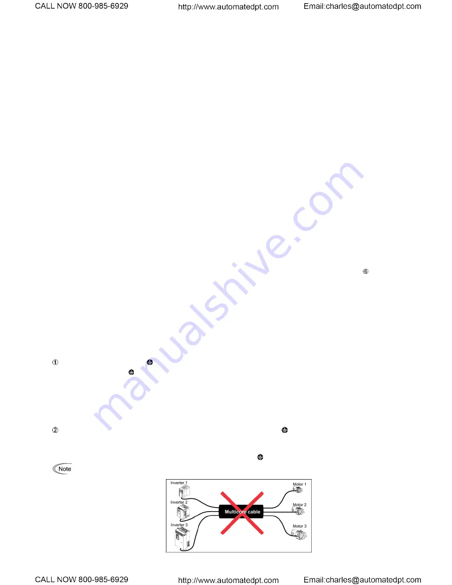
When there is more than one combination of an inverter and motor, do not use a multi-conductor cable for the 
purpose of running the leads together. 


Summary of Contents for EQ7 Series

Page 1: ......

Page 2: ...e sound knowledge of the device and familiarize yourself with all safety information and precautions before proceeding to operate the inverter Safety precautions are classified into the following two categories in this manual Failure to heed the information indicated by this symbol may lead to dangerous conditions possibly resulting in death or serious bodily injuries Failure to heed the informati...

Page 3: ...1 2 Mounting and Wiring the Inverter 2 1 2 1 Operating Environment 2 1 2 2 Installing the Inverter 2 1 2 3 Wiring 2 4 2 4 Mounting and Connecting the Keypad 2 27 2 5 Input Power and Motor Connection 2 28 3 Operation using the Keypad 3 1 3 1 LED Monitor LCD Monitor and Keys 3 1 3 2 Overview of Operating Modes 3 3 3 3 Running Mode 3 4 3 4 Programming Mode 3 8 4 Function Codes Parameters 4 1 4 1 Func...

Page 4: ...cations 9 1 9 1 What is PID Control 9 1 9 2 Connect Transducer Feedback Signal 9 2 9 3 Setpoint Scaling Transducer Feedback Scaling 9 4 10 Troubleshooting 10 1 10 1 Protective Functions 10 1 10 2 Before Proceeding with Troubleshooting 10 2 10 3 If Neither an Alarm Nor Light Alarm Indication Appears on the LED Monitor 10 5 10 4 If an Alarm Code Appears on the LED Monitor 10 12 10 5 If the Light Ala...

Page 5: ...with a capacity of 50 HP or above whose protective structure is IP00 Open Chassis involve a possibility that a human body may touch the live conductors of the main circuit terminal block Inverters to which an optional DC reactor is connected also involve the same Install such inverters in an inaccessible place Otherwise electric shock or injuries could occur Do not support the inverter by its fron...

Page 6: ... or more the inverter rated capacity Otherwise a fire could occur Ground the inverter in compliance with the national or local electric code Be sure to ground the inverter s grounding terminals G Otherwise an electric shock or a fire could occur Qualified electricians should carry out wiring Be sure to perform wiring after turning the power OFF Otherwise an electric shock could occur Be sure to pe...

Page 7: ...on or frequency different from the commanded ones Design the machine so that safety is ensured even in such cases If any of the protective functions have been activated first remove the cause Then after checking that the all run commands are set to OFF release the alarm If the alarm is released while any run commands are set to ON the inverter may supply the power to the motor running the motor Ot...

Page 8: ...the operation sequence to cause a sudden motor start or an unexpected motor operation An accident or injuries could occur Maintenance inspection and parts replacement Before proceeding to the maintenance inspection jobs turn OFF the power and wait at least five minutes for inverters of 40 HP or below or at least ten minutes for inverters of 50 HP or above Make sure that the LED monitor and chargin...

Page 9: ...rated for 230 V class input Suitable For Use On A Circuit Of Delivering Not More Than 100 000 rms Symmetrical Amperes 480 Volts Maximum when protected by Class J Fuses or a Circuit Breaker having an interrupting rating not less than 100 000 rms Symmetrical Amperes 480 Volts Maximum Models FRN rated for 460 V class input Integral solid state short circuit protection does not provide branch circuit ...

Page 10: ... 3 3 7 5 EQ7 2007 C 60 50 30 9 3 5 8 8 4 2 3 8 8 4 2 3 EQ7 2010 C CT 10 5 VT 75 75 EQ7 2015 C CT 15 7 5 VT 100 100 6 13 3 EQ7 2020 C CT 20 10 VT 150 125 4 21 2 6 13 3 EQ7 2025 C CT 51 3 5 8 3 26 7 4 21 2 25 VT 175 150 1 42 4 3 26 7 3 26 7 4 21 2 EQ7 2030 C CT 30 15 VT 200 175 2 33 6 2 3 2 33 6 3 26 7 EQ7 2040 C CT 40 20 VT 250 200 2 0 67 4 2 33 6 2 3 EQ7 2050 C CT 119 4 13 5 1 42 4 50 25 VT 350 25...

Page 11: ... 8 4 10 EQ7 4025 C CT 51 3 5 8 6 13 3 6 13 3 6 13 3 6 13 3 25 VT 90 75 EQ7 4030 C CT 30 15 VT 100 100 4 21 2 EQ7 4040 C CT 40 20 VT 125 125 3 26 7 4 21 2 4 21 2 EQ7 4050 C CT 119 4 13 5 2 33 6 2 33 6 50 25 VT 175 2 33 6 3 26 7 EQ7 4060 C CT 60 30 VT 200 150 2 33 6 2 3 EQ7 4075 C CT 75 VT 250 200 1 0 53 5 2 3 EQ7 4100 C CT 100 40 VT 175 1 0 53 5 EQ7 4125 C CT 238 9 27 10 6 1 2 2 0 67 4 4 0 107 2 14...

Page 12: ...2 2 4 450 800 300 2 152 2 350 2 177 2 150 EQ7 4600 C CT 500 EQ7 4500 C VT 1200 400 2 203 2 400 2 203 2 EQ7 4600 C CT 150 EQ7 4700 C CT 600 200 EQ7 4600 C VT 1200 500 2 253 2 500 2 253 2 EQ7 4700 C CT 200 EQ7 4800 C CT 700 EQ7 4700 C VT 1400 600 2 304 2 600 2 304 2 EQ7 4800 C CT 800 250 VT 1600 350 3 177 3 400 3 203 3 EQ7 4900 C CT 900 300 VT 2000 1400 500 3 253 3 600 3 304 3 EQ7 41000 C CT 1000 40...

Page 13: ...tion there should be no dents or parts missing 3 The EQ7 drive is the type you ordered You can check the type and specifications on the main nameplate Main and sub nameplates are attached to the EQ7 drive and are located as shown below 4 Check that the input voltage range meets the input power requirements 5 Ensure that for variable torque applications the motor rated current matches the variable ...

Page 14: ...tal EQ7 2075 C 75 60 Sheet Metal EQ7 2100 C 100 75 Sheet Metal EQ7 2125 C 125 100 Sheet Metal EQ7 2150 C 150 125 Sheet Metal 460V EQ7 40P5 C 0 5 0 5 Plastic EQ7 4001 C 1 1 Plastic EQ7 4002 C 2 2 Plastic EQ7 4003 C 3 3 Plastic EQ7 4005 C 5 5 Plastic EQ7 4007 C 7 5 7 5 Plastic EQ7 4010 C 10 7 5 Plastic EQ7 4015 C 15 10 Plastic EQ7 4020 C 20 15 Plastic EQ7 4025 C 25 20 Plastic EQ7 4030 C 30 25 Plasti...

Page 15: ...m free from influence of the conductive dust Wiredrawing machines metal processing extruding machines printing presses combustors and industrial waste treatment A lot of fibrous or paper dust Fibrous or paper dust accumulated on the heat sink lowers the cooing effect Entry of dust into the inverter causes the electronic circuitry to malfunction Any of the following measures may be necessary Mount ...

Page 16: ...le with 460 V series motors in particular is particularly long surge voltage will deteriorate motor insulation To prevent this use the following guidelines Inverter 7 5 HP and larger Motor Insulation Level 1000 V 1300 V 1600 V 460 VAC Input Voltage 66 ft 20 m 328 ft 100 m 1312 ft 400 m 230 VAC Input Voltage 1312 ft 400 m 1312 ft 400 m 1312 ft 400 m Inverter 5 HP and smaller Motor Insulation Level ...

Page 17: ...hyristor driven loads If no DCR is used the percentage reactance of the power supply decreases and harmonic components and their peak levels increase These factors may break rectifiers or capacitors in the converter section of the inverter or decrease the capacitance of the capacitors If the input voltage unbalance rate is 2 to 3 use an optional AC reactor ACR 3 61800 IEC 67 V voltage average phas...

Page 18: ...1 0 5 EQ7 2001 C 10 2 1 EQ7 2002 C 10 15 3 1 5 EQ7 2003 C 20 5 3 EQ7 2005 C 20 30 7 5 EQ7 2007 C 30 50 EQ7 2010 C CT 10 5 VT 40 75 EQ7 2015 C CT 15 7 5 VT 50 100 EQ7 2020 C CT 20 10 VT 75 125 EQ7 2025 C CT 25 VT 100 150 EQ7 2030 C CT 30 15 VT 175 EQ7 2040 C CT 40 20 VT 150 200 EQ7 2050 C CT 50 25 VT 175 250 EQ7 2060 C CT 60 30 VT 200 300 EQ7 2075 C CT 75 VT 250 350 EQ7 2100 C CT 100 VT 350 40 EQ7 ...

Page 19: ...C VT EQ7 4800 C CT 800 250 VT EQ7 4900 C CT 900 300 VT 1400 EQ7 41000 C CT 1000 400 VT 1600 If no zero phase current earth leakage current detective device such as a ground fault relay is installed in the upstream power supply line in order to avoid the entire power supply system s shutdown undesirable to factory operation install a residual current operated protective device RCD earth leakage cir...

Page 20: ...ic contactor MC is inserted in the inverter s output secondary circuit for switching the motor to a commercial power or for any other purposes it should be switched on and off when both the inverter and motor are completely stopped This prevents the contact point from getting rough due to a switching arc of the MC The MC should not be equipped with any main circuit surge killer Applying a commerci...

Page 21: ...or a motor If any of the problems listed below occurs take an appropriate measure against them Problem Measures An earth leakage circuit breaker that is connected to the input primary side has tripped With overcurrent protection 1 Decrease the carrier frequency 2 Make the wires between the inverter and motor shorter 3 Use an earth leakage circuit breaker with lower sensitivity than the one current...

Page 22: ...CODES of the user manual 1 4 Precautions in using special motors When using special motors please read the following section Explosion proof motors When driving an explosion proof motor with an inverter use a combination of a motor and an inverter that has been approved in advance Submersible motors and pumps These motors have a larger rated current than general purpose motors Select an inverter w...

Page 23: ...Output current exceeding the limit extremely increases voltage ripples on the DC link bus impeding normal operation or resulting in an inverter breakdown Wiring When connecting 230 V inverters of 60 HP or above or 460 V ones of 125 HP or above to single phase power use L1 and L3 phases since cooling fans and magnetic contactors inside the inverter are supplied with power via L1 and L3 Using L2 doe...

Page 24: ...entilation inside the panel as the surrounding temperature easily rises Do not mount the inverter in a small panel with poor ventilation When mounting two or more inverters When mounting two or more inverters in the same unit or panel install them side by side When one must be mounted above the other be sure to separate them with a partition plate or the like so that any heat radiating from an inv...

Page 25: ...7 4050 C EQ7 4100 C M6 20 5 pcs for upper side 3 pcs for lower side M6 20 2 pcs for upper side 51 3 5 8 EQ7 2075 C EQ7 4100 C EQ7 4125 C M6 20 3 pcs each for upper and lower sides M6 12 3 pcs for upper side 51 3 5 8 EQ7 2125 C EQ7 4150 C EQ7 4200 C M5 12 7 pcs each for upper and lower sides M5 12 7 pcs for upper side 31 0 3 5 EQ7 4250 C EQ7 4300 C M5 16 7 pcs each for upper and lower sides M5 16 7...

Page 26: ...the specified screws Otherwise a fire or accident could occur 3 Mounting notes The EQ7 2007 C EQ7 4007 C through EQ7 2040 C EQ7 4040 C should be mounted with four screws or bolts using screw holes A or B shown below Note that at each of the top and bottom of the inverter the two screws or bolts should be located in a bilaterally symmetrical position ...

Page 27: ...cover back into place in the reverse order of removal Figure 2 4 Removing the Front Cover and the Wiring Guide e g EQ7 4020 C 2 For inverters of 50 to 1000 HP Loosen the four front cover fixing screws hold the cover with both hands slide it upward slightly and pull it forward as shown below After carrying out wiring see Sections 2 3 2 through 2 3 6 align the screw holes provided in the front cover...

Page 28: ... C EQ7 4001 C EQ7 2002 C EQ7 4002 C Figure B M4 15 9 1 8 M4 15 9 1 8 M3 5 10 6 1 2 EQ7 2003 C EQ7 4003 C EQ7 2005 C EQ7 4005 C EQ7 2007 C EQ7 4007 C Figure C M5 31 0 3 5 M5 31 0 3 5 EQ7 2010 C EQ7 4010 C EQ7 2015 C EQ7 4015 C EQ7 2020 C EQ7 4010 C EQ7 2025 C EQ7 4025 C Figure D M6 51 3 5 8 M6 51 3 5 8 EQ7 2030 C EQ7 4030 C EQ7 2040 C EQ7 4040 C EQ7 2050 C EQ7 4050 C Figure E M8 119 13 5 M8 119 13 ...

Page 29: ...2 6 Unit inch mm Refer to Section 2 3 3 9 ...

Page 30: ...Q7 4003 C EQ7 4003 C EQ7 4003 C EQ7 4005 C EQ7 4005 C EQ7 4005 C 12 3 3 EQ7 4007 C EQ7 4007 C EQ7 4007 C 12 3 3 10 5 3 12 3 3 12 3 3 EQ7 4010 C EQ7 4010 C EQ7 4010 C EQ7 4015 C 10 5 3 10 5 3 EQ7 4015 C EQ7 4015 C 8 8 4 10 5 3 8 8 4 EQ7 4020 C EQ7 4020 C EQ7 4020 C 8 8 4 8 8 4 EQ7 4025 C 6 13 3 6 13 3 EQ7 4025 C EQ7 4025 C EQ7 4030 C 6 13 3 EQ7 4030 C EQ7 4030 C EQ7 4040 C EQ7 4040 C EQ7 4040 C 4 2...

Page 31: ...minal to prevent electric shock fire or other disasters and to reduce electric noise 4 Use crimp terminals covered with insulated sleeves for the main circuit terminal wiring to ensure a reliable connection 5 Keep the power supply wiring primary circuit and motor wiring secondary circuit of the main circuit and control circuit wiring as far away as possible from each other 6 After removing a screw...

Page 32: ...rcuit terminal block cannot be routed straight into the terminal Route such wires as shown below so that the front cover can be reinstalled 9 For inverters of 900 and 1000 HP two L2 S input terminals are arranged vertically to the terminal block When connecting wires to these terminals use the bolts washers and nuts that come with the inverter as shown below ...

Page 33: ... inverter s output secondary circuit Doing so could cause a fire Ground the inverter in compliance with the national or local electric code Be sure to ground the inverter s grounding terminals G Otherwise an electric shock or fire could occur Qualified electricians should carry out wiring Be sure to perform wiring after turning the power OFF Otherwise electric shock could occur Be sure to perform ...

Page 34: ...2 11 2 3 4 Wiring of main circuit terminals and grounding terminals This section shows connection diagrams with the Enable input function used SINK mode input by factory default ...

Page 35: ...more Never install them in the same wire duct When crossing the control circuit wiring with the main circuit wiring set them at right angles 9 The connection diagram shows factory default functions assigned to digital input terminals X1 to X7 FWD and REV transistor output terminals Y1 to Y4 and relay contact output terminals Y5A C and 30A B C 10 Switching connectors in the main circuits For detail...

Page 36: ...o 40 Built in None External DC braking resistor 2 3 For inverters of 15 HP or below if the capacity of the built in DC braking resistor DBR is insufficient since the inverter undergoes frequent start stop or heavy inertial load mount an optional external DC braking resistor DBR with a larger capacity to increase the braking capability using the following steps Before mounting the external DBR remo...

Page 37: ... a PWM converter is connectable to these terminals When you need to use the DC link bus terminals P and N consult your TECO Westinghouse Motor Company representative Switching connectors Power switching connectors CN UX on inverters of 125 HP or above for 460 V Inverters of 125 HP or above for 460 V are equipped with a set of switching connectors male which should be configured according to the po...

Page 38: ... terminals R1 and T1 Feeding the DC linked power Combined with a PWM converter By factory default the fan power supply switching connectors CN R and CN W are set on the FAN and NC positions respectively Do not exchange them unless you drive the inverter with a DC linked power supply Wrong configuration of these switching connectors cannot drive the cooling fans causing a heat sink overheat alarm 0...

Page 39: ... to the auxiliary control power input terminals R0 and T0 If the inverter main power is shut down however no power is supplied to the control circuit so that the inverter cannot issue a variety of output signals or display on the keypad To retain an alarm output signal ALM issued on inverter s programmable output terminals by the protective function or to keep the keypad alive even if the main pow...

Page 40: ...230 V and those of 125 HP or above for 460 V are equipped with terminals R1 and T1 Only if the inverter works with the DC linked power input whose source is a PWM converter these terminals are used to feed AC power to the fans while they are not used in any power system of ordinary configuration In this case set up the fan power supply switching connectors CN R and CN W Terminal rating 200 to 220 ...

Page 41: ...e to such noise An accident could occur Connecting disconnecting wires to from a control circuit terminal of spring screwless type Strip the wire end by 8 to 10 mm 0 31 to 0 39 inch as shown below Strip length of wire end 8 to 10 mm 0 31 to 0 39 inch Type of screwdriver tip shape Flat 0 6 3 5 mm 0 024 0 14 inch For strand wires the strip length specified above should apply after twisting of them I...

Page 42: ...uxiliary frequency command setting ratio setting torque limiter level setting or analog input monitor can be assigned to this terminal 3 Hardware specifications Input impedance 250 The maximum input is 30 mA DC however the current larger than 20 mA DC is handled as 20 mA DC PTC NTC thermistor input 1 Connects PTC Positive Temperature Coefficient NTC Negative Temperature Coefficient thermistor for ...

Page 43: ...tal input 1 1 Various signals such as Coast to a stop Enable external alarm trip and Select multi frequency can be assigned to terminals X1 to X7 FWD and REV by setting function codes E01 to E07 E98 and E99 For details refer to Chapter 4 Section 4 2 Details of Function Codes 2 Input mode i e SINK SOURCE is changeable by using the slide switch SW1 Refer to Instruction manual section 2 3 6 Setting u...

Page 44: ...ntact to turn X1 to X7 FWD or REV ON or OFF Figure 2 14 shows two examples of a circuit that uses a relay contact to turn control signal input X1 to X7 FWD or REV ON or OFF In circuit a the slide switch SW1 is turned to SINK whereas in circuit b it is turned to SOURCE Note To configure this kind of circuit use a highly reliable relay PLC Photocoupler CM Control circuit X1 to X7 FWD REV 24 VDC SOUR...

Page 45: ...s 1k 2 W Check if the pulse train is correctly transmitted because stray capacity is significantly affected by the wire types and wiring conditions Analog output FM1 FM2 Analog monitor Both terminals output monitor signals for analog DC voltage 0 to 10 V or analog DC current 4 to 20 mA The output form VO IO for each of FM1 and FM2 can be switched with the slide switches on the control PCB and the ...

Page 46: ...e power 24 VDC allowable range 22 to 27 VDC 100 mA max through the PLC terminal Short circuit between the terminals CMY and CM in this case CMY Transistor output common Common terminal for transistor output signals This terminal is electrically isolated from terminals CM and 11 s Connecting programmable logic controller PLC to terminal Y1 Y2 Y3 or Y4 Figure 2 17 shows two examples of circuit conne...

Page 47: ... control PCB A communications port transmits data through the RS 485 multipoint protocol between the inverter and a computer or other equipment such as a PLC For setting of the terminating resistor refer to Section 2 3 6 Setting up the slide switches RJ 45 connector for the keypad RS 485 communications port 1 Standard RJ 45 connector 1 Used to connect the inverter with the keypad The inverter supp...

Page 48: ...t ten minutes for those of 50 HP or above Make sure that the LED monitor and charging lamp are turned OFF Further make sure using a multimeter or a similar instrument that the DC link bus voltage between the terminals P and N has dropped to the safe level 25 VDC or below An electric shock may result if this warning is not heeded as there may be some residual electric charge in the DC bus capacitor...

Page 49: ...tting of SW4 and SW6 also change the data of function codes F29 and F32 respectively Output form FM1 FM2 SW4 F29 data SW6 F32 data Voltage output Factory default VO1 0 VO2 0 Current output IO1 1 IO2 1 SW5 Switches the property of the analog input terminal C1 between analog setting current input PTC thermistor input and NTC thermistor input When changing this switch setting also change the data of ...

Page 50: ...ad from the inverter pull it forward while holding down the hook pointed by the arrow in Figure 2 22 When mounting it put the keypad back into place in the reverse order of removal Figure 2 22 Removing the Keypad RJ 45 connector M3 x 12 Coarse thread tapping screws Panel Inside the panel Mount the keypad with four M3 x 12 screws provided two fine thread screws and two coarse thread tapping screws ...

Page 51: ...er has been turned OFF wait at least ten minutes until the charge indicator extinguishes completely before touching any wiring circuit boards or components MOTOR U V W 3Ø Induction motor Use L1 L2 L3 for 3Ø Input Power Connect frame to ground Input Protection Fuse or Magnetic Contactor To change direction of motor rotation swap any two of the three motor leads L1 L2 L3 R L1 S L2 T L3 U T1 V T2 W T...

Page 52: ...als U V and W Also check that the grounding wires are connected to the grounding terminals G correctly See Figure 2 23 2 Check the control circuit terminals and main circuit terminals for short circuits or ground faults 3 Check for loose terminals connectors and screws 4 Check that the motor is separated from mechanical equipment 5 Make sure that all switches of devices connected to the inverter a...

Page 53: ...g mode Same as above In Alarm mode Alarm code which identifies the alarm when the protective function is activated LCD monitor which displays the following according to the operation modes In Run mode Running status information In Programming mode Menus function codes and their settings In Alarm mode Alarm code which identifies the alarm when the protective function is activated Indication Units I...

Page 54: ...ode and establishes the newly entered data In Alarm mode Pressing this key displays the details of the problem indicated by the alarm code that has come up on the LED monitor Operation keys Starts running the motor in the forward rotation Starts running the motor in the reverse rotation Stops the motor Holding down this key for more than 1 second toggles between local and remote modes LED lamp Lig...

Page 55: ...riety of information relating to the inverter status and maintenance Alarm Mode If an alarm condition arises the inverter automatically enters the Alarm mode in which you can view the corresponding alarm code and its related information on the LED and LCD monitors Alarm code that represents the cause s of the alarm s that has been triggered by the protective function For details refer to the Prote...

Page 56: ...status on the LCD monitor 1 When function code E45 LCD monitor item selection is set at 0 The LCD monitor displays the running status the rotational direction and the operation guide The upper indicators show the unit of values displayed on the LED monitor as detailed in Section 3 3 2 The lower ones show the running status and run command source Figure 3 3 Display of Running Status The running sta...

Page 57: ...nitor page of the items supported Table 3 4 Items Monitored Monitored Items on the LED Monitor Example Unit Meaning of Displayed Value Function code E43 Monitor page Speed Monitor Function code E48 specifies what to be displayed 0 0 Output frequency 1 before slip compensation Hz Frequency actually being output Hz E48 0 Output frequency 2 after slip compensation Hz Frequency actually being output H...

Page 58: ...netic flux command Note 3 Magnetic flux command value Available only under vector control 24 22 Input watt hour kWh Input watt hour kWh 100 25 23 The LCD monitor given below shows information related to the item shown on the LED monitor The monitor items on the LED monitor can be switched by pressing the key Figure 3 5 LCD Monitor Sample Detailed for the LED Monitor Item Note 1 These PID related i...

Page 59: ...mming mode by pressing the key and select LALM1 on Menu 5 Maintenance Information It is also possible to check the last three light alarms by selecting LALM2 last to LALM4 3rd last For details of the menu transition of the maintenance information refer to Section 3 4 6 Reading maintenance information How to remove the current light alarm After checking the current light alarm to switch the LED mon...

Page 60: ...Drive Monitoring Display the running information required for maintenance or test running 3 4 4 4 I O Checking Display external interface information 3 4 5 5 Maintenance Information Display maintenance information including cumulative run time 3 4 6 6 Alarm Information Display the recent four alarm codes Also this menu is used to view the information on the running status at the time the alarm occ...

Page 61: ...n F codes Fundamental functions Functions concerning basic motor running E codes Extension terminal functions Functions concerning the assignment of control circuit terminals Functions concerning the display of the LED monitor C codes Control functions Functions associated with frequency settings P codes Motor 1 parameters Functions for setting up characteristics parameters such as capacity of the...

Page 62: ...n guides The function code data modification screen shows the function code its name its data before and after change allowable entry range and operation guides Before change Function code name Function code that has been changed from factory default Data Allowable entry range Operation guide Changing data Data before change Data being changed Figure 3 9 Screen Samples for Changing Function Code D...

Page 63: ...the function code data The data will be saved in the inverter s memory The display returns to a list of function codes and the cursor moves to the next function code F04 in this example Pressing the key instead of the key cancels the new function code data reverts to the previous data returns to a list of function codes and returns the cursor to the previous function code F03 in this example 6 Pre...

Page 64: ...frequency after slip compensation Output current Iout Output current Output voltage Vout Output voltage 2 Calculated torque TRQ Calculated output torque generated by motor Reference frequency Fref Frequency specified by a frequency command Running direction FWD REV Blank Forward Reverse Stopped Current limit IL Current limiting Undervoltage Voltage limit LU VL Undervoltage detected Voltage limitin...

Page 65: ...ti When this setting is 100 the LED monitor shows 1 00 time of the value to be displayed Magnetic flux command value FLUX Flux command value in Deviation in SY synchronous operation SY d Deviation in SY synchronous operation 8 Current position pulse 4 multiplied P4 Current position pulse for positioning control Stop position target pulse 4 multiplied E4 Stop position target pulse for positioning c...

Page 66: ...nd value Deviation in SY synchronous operation Current position pulse Stop position target pulse Position deviation pulse Reserved End of page Common operation items To access the target data switch to the desired page using the and keys This page continues to the next page This page is continued from the previous page and continues to the next page This page is continued from the previous page Fi...

Page 67: ...terminal 12 C1 Input current on terminal C1 V2 Input voltage on terminal V2 6 Analog output signals FM1 FM1 FM2 FM2 Output voltage on terminal FM1 Output current on terminal FM1 Output voltage on terminal FM2 Output current on terminal FM2 7 Input signals on the digital input interface card option Di o Input signals on the option card in hexadecimal Output signals on the digital output interface c...

Page 68: ...hlighted when 1 Normal when 0 Highlighted when ON Normal when OFF Input signals at the control circuit terminal block Output signal Input signals via communications link See Note 1 on the next page Input voltage at terminal 12 Input current at terminal C1 Input voltage at terminal V2 Output voltage at terminal FM1 Output current at terminal FM1 Output voltage at terminal FM2 Output current at term...

Page 69: ...t terminal CS Common operation items To access the target data switch to the desired page using the and keys This page continues to the next page This page is continued from the previous page and continues to the next page This page is continued from the previous page Figure 3 13 Screen Transition for I O Checking Note shown on the display indicates an option card that is not installed PG pulse ra...

Page 70: ...ory N Impossible Copying data The keypad is capable of copying of the function code data stored in the inverter s memory into the keypad s memory refer to Menu 7 Data copying in Programming mode With this feature you can easily transfer the data saved in a source inverter to other destination inverters If the specifications of the source and destination inverters differ some code data may not be c...

Page 71: ...control Dynamic torque control w o PG Vector control without speed sensor w PG Vector control with speed sensor Torque control Torque Vector control with without speed sensor For details about the drive control refer to Function code F42 Drive Control Selection 1 The EQ7 is a general purpose inverter whose operation is customized by frequency basis function codes like conventional inverters Under ...

Page 72: ...cceleration Time 1 0 00 to 6000 s Note Entering 0 00 cancels the acceleration time requiring external soft start Y Y 1 Y Y Y N 4 37 F08 Deceleration Time 1 Y Y 1 Y Y Y N F09 Torque Boost 1 0 0 to 20 0 percentage with respect to Rated Voltage at Base Frequency 1 Y Y 0 0 Y N N N 4 40 4 56 F10 Electronic Thermal Overload Protection for Motor 1 Select motor characteristics 1 For a general purpose moto...

Page 73: ...ut frequency 1 before slip compensation 1 Output frequency 2 after slip compensation 2 Output current 3 Output voltage 4 Output torque 5 Load factor 6 Input power 7 PID feedback amount PV 8 PG feedback value 9 DC link bus voltage 10 Universal AO 13 Motor output 14 Calibration 15 PID command SV 16 PID output MV Y Y 0 Y Y Y Y 17 Positional deviation in synchronous run mode N N Y N F32 Analog Output ...

Page 74: ...e at constant speed Disable during ACC DEC 2 Enable during ACC constant speed operation Y Y 2 Y N N N 4 67 F44 Level 20 to 200 The data is interpreted as the rated output current of the inverter for 100 Y Y 5 Y N N N F50 Electronic Thermal Overload Protection for Braking Resistor Discharging capability 0 Braking resistor built in type 1 to 9000 kWs OFF Disable Y Y1 Y2 6 Y Y Y Y 4 68 F51 Allowable ...

Page 75: ...itch normal inverse operation IVS Y Y Y N 22 1022 Interlock IL Y Y Y Y 23 1023 Cancel torque control Hz TRQ N N N Y 24 1024 Enable communications link via RS 485 or fieldbus option LE Y Y Y Y 25 1025 Universal DI U DI Y Y Y Y 26 1026 Enable auto search for idling motor speed at starting STM Y Y N Y 30 1030 Force to stop STOP 30 Active OFF 1030 Active ON Y Y Y Y 32 1032 Pre excitation EXITE N Y Y N...

Page 76: ...witch motor drive source between commercial power and inverter output For secondary side SW52 2 Y N N N 13 Switch motor drive source between commercial power and inverter output For primary side SW52 1 Y N N N 15 1015 Select AX terminal function For MC on primary side AX Y Y Y Y 22 1022 Inverter output limiting with delay IOL2 Y Y Y Y 25 1025 Cooling fan in operation FAN Y Y Y Y 26 1026 Auto reset...

Page 77: ... E36 Frequency Detection 2 Level 0 0 to 500 0 Hz Y Y 60 0 Y Y Y Y 4 96 E37 Current Detection 2 Low Current Detection Level 0 00 Disable Current value of 1 to 200 of the inverter rated current Y Y1 Y2 2 Y Y Y Y 4 96 E38 Timer 0 01 to 600 00 s Y Y 10 00 Y Y Y Y 4 96 E40 PID Display Coefficient A 999 to 0 00 to 9990 Y Y 100 Y Y Y N 4 96 E41 PID Display Coefficient B 999 to 0 00 to 9990 Y Y 0 00 Y Y Y...

Page 78: ...cting function code data assigns the corresponding function to terminals FWD and REV as listed below 4 71 4 104 E98 Terminal FWD Function 0 1000 Select multi frequency 0 to 1 steps SS1 N Y 98 Y Y Y N E99 Terminal REV Function 1 1001 Select multi frequency 0 to 3 steps SS2 N Y 99 Y Y Y N 2 1002 Select multi frequency 0 to 7 steps SS4 Y Y Y N 3 1003 Select multi frequency 0 to 15 steps SS8 Y Y Y N 4...

Page 79: ...ommand LOCK N N Y N 49 1049 Pulse train sign SIGN 59 1059 Enabled battery operation BATRY Y Y Y Y Y Y Y Y 70 1070 Cancel constant peripheral speed control Hz LSC Y Y Y N 71 1071 Hold the constant peripheral speed control frequency in the memory LSC HLD Y Y Y N 72 1072 Count the run time of commercial power driven motor 1 CRUN M1 Y N N Y 73 1073 Count the run time of commercial power driven motor 2...

Page 80: ... switching available 11 Digital input interface card option 12 Pulse train input N Y 2 Y Y Y N 4 26 4 107 C31 Analog Input Adjustment for 12 Offset 5 0 to 5 0 Y Y 0 0 Y Y Y Y 4 107 C32 Gain 0 00 to 400 00 Y Y 100 00 Y Y Y Y C33 Filter time constant 0 00 to 5 00 s Y Y 0 05 Y Y Y Y C34 Gain base point 0 00 to 100 00 Y Y 100 00 Y Y Y Y C35 Polarity 0 Bipolar 1 Unipolar N Y 1 Y Y Y Y C36 Analog Input ...

Page 81: ... loss factor 1 0 00 to 20 00 Y Y1 Y2 7 Y Y Y Y P14 Iron loss factor 2 0 00 to 20 00 Y Y1 Y2 0 00 Y Y Y Y P15 Iron loss factor 3 0 00 to 20 00 Y Y1 Y2 0 00 Y Y Y Y P16 Magnetic saturation factor 1 0 0 to 300 0 Y Y1 Y2 7 Y Y Y Y P17 Magnetic saturation factor 2 0 0 to 300 0 Y Y1 Y2 7 Y Y Y Y P18 Magnetic saturation factor 3 0 0 to 300 0 Y Y1 Y2 7 Y Y Y Y P19 Magnetic saturation factor 4 0 0 to 300 0...

Page 82: ... Y Y N H18 Torque Control Mode selection 0 Disable Speed control 2 Enable Torque current command 3 Enable Torque command N Y 0 N Y Y Y H26 Thermistor for motor Mode selection 0 Disable 1 PTC The inverter immediately trips with 0h4 displayed 2 PTC The inverter issues output signal THM and continues to run 3 NTC When connected Y Y 0 Y Y Y Y H27 Level 0 00 to 5 00 V Y Y 0 35 Y Y Y Y H28 Droop Control...

Page 83: ...y limiter Low decelerate to stop the motor Y Y 0 Y Y Y N H64 Lower limiting frequency 0 0 Depends on F16 Frequency limiter Low 0 1 to 60 0 Hz Y Y 1 6 Y N N N H65 Non linear V f Pattern 3 Frequency 0 0 Cancel 0 1 to 500 0 Hz N Y 0 0 Y N N N H66 Voltage 0 to 240 Output an AVR controlled voltage for 230 V series 0 to 500 Output an AVR controlled voltage for 460 V series N Y2 0 Y N N N H67 Auto Energy...

Page 84: ... H88 Reserved 9 H89 Reserved 9 H90 Reserved 9 H91 PID Feedback Wire Break Detection 0 0 Disable alarm detection 0 1 to 60 0 s Y Y 0 0 Y Y Y N H92 Continuity of Running P 0 000 to 10 000 times 999 Y Y1Y2 999 Y N N N H93 I 0 010 to 10 000 s 999 Y Y1Y2 999 Y N N N H94 Cumulative Motor Run Time 1 0 to 99990 hours The cumulative run time can be modified or reset N N Y Y Y Y H95 DC Braking Braking respo...

Page 85: ...tant 0 5 to 75 0 min Y Y 3 Y Y Y Y A09 DC Braking 2 Braking starting frequency 0 0 to 60 0 Hz Y Y 0 0 Y Y Y N A10 Braking level 0 to 80 LD MD mode 4 0 to 100 HD mode Y Y 0 Y Y Y N A11 Braking time 0 00 Disable 0 01 to 30 00 s Y Y 0 00 Y Y Y N A12 Starting Frequency 2 0 0 to 60 0 Hz Y Y 0 5 Y Y Y N A13 Load Selection Auto Torque Boost Auto Energy Saving Operation 2 0 Variable torque load 1 Constant...

Page 86: ...0 0 to 300 0 Y Y1 Y2 7 Y Y Y Y A34 Magnetic saturation factor 5 0 0 to 300 0 Y Y1 Y2 7 Y Y Y Y A35 Magnetic saturation extension factor a 0 0 to 300 0 Y Y1 Y2 7 Y Y Y Y A36 Magnetic saturation extension factor b 0 0 to 300 0 Y Y1 Y2 7 Y Y Y Y A37 Magnetic saturation extension factor c 0 0 to 300 0 Y Y1 Y2 7 Y Y Y Y A39 Motor 2 Selection 0 Motor characteristics 0 Consult Factory 1 Motor characteris...

Page 87: ... Torque current under vector control 0 00 to 2000 A N Y1 Y2 7 N Y Y Y A56 Induced voltage factor under vector control 50 to 100 N Y1 Y2 85 90 8 N Y Y Y A57 Reserved 9 7 The motor parameters are automatically set depending upon the inverter s capacity See Table B 8 85 for inverters of 150 HP or less 90 for those of 175 HP or above 9 Factory use Do not access these function codes 11 Refer to the Use...

Page 88: ...Y Y Y N J21 Dew Condensation Prevention Duty 1 to 50 Y Y 1 Y Y Y Y J22 Commercial Power Switching Sequence 0 Keep inverter operation Stop due to alarm 1 Automatically switch to commercial power operation N Y 0 Y N N Y J56 PID Control Speed command filter 0 00 to 5 00 s Y Y 0 10 Y Y Y N J57 Dancer reference position 100 to 0 to 100 Y Y 0 Y Y Y N J58 Detection width of dancer position deviation 0 Di...

Page 89: ...ssing 0 Continue to run 1 1 Stop running with alarm 1 2 Stop running with alarm 2 3 Continue to run 2 4 Stop running with alarm 3 5 Stop running with alarm 4 N Y 2 N Y Y Y d24 Zero Speed Control 0 Not permit at startup 1 Permit at startup N Y 0 N Y Y N d25 ASR Switching Time 0 000 to 1 000 s Y Y 0 000 N Y Y Y d32 Torque Control Speed limit 1 0 to 110 Y Y 100 N Y Y Y d33 Speed limit 2 0 to 110 Y Y ...

Page 90: ...Y 999 N N Y N d74 APR negative output limiter 20 to 200 999 No limiter Y Y 999 N N Y N d75 Z phase alignment gain 0 00 to 10 00 times Y Y 1 00 N N Y N d76 Synchronous offset angle 0 to 359 degrees Y Y 0 N N Y N d77 Synchronization completion detection angle 0 to 100 degrees Y Y 15 N N Y N d78 Excessive deviation detection range 0 to 65535 in units of 10 pulses Y Y 65535 N N Y N d98 Reserved 9 d99 ...

Page 91: ...timer y13 If the retry fails trip with alarm erp If it succeeds continue to run 3 Continue to run Y Y 0 Y Y Y Y y13 Timer 0 0 to 60 0 s Y Y 2 0 Y Y Y Y y14 Baud rate 0 2400 bps 1 4800 bps 2 9600 bps 3 19200 bps 4 38400 bps Y Y 3 Y Y Y Y y15 Data length 0 8 bits 1 7 bits Y Y 0 Y Y Y Y y16 Parity check 0 None 2 stop bits 1 Even parity 1 stop bit 2 Odd parity 1 stop bit 3 None 1 stop bit Y Y 0 Y Y Y ...

Page 92: ...0 3 200 5 250 2 0 7 300 10 350 2 5 15 450 20 1 0 500 25 600 4 0 30 700 40 800 5 0 50 900 60 1000 75 1 5 Inverter capacity HP Auto restart after momentary power failure H13 Inverter capacity HP Auto restart after momentary power failure H13 0 5 0 5 100 1 5 1 125 2 150 3 200 5 250 2 0 7 300 10 350 2 5 15 450 20 1 0 500 25 600 4 0 30 700 40 800 5 0 50 900 60 1000 75 1 5 ...

Page 93: ...4 24 Table B Motor Parameters When the HP rating motors is selected with P99 A39 data 1 Three phase 230 V series EQ7 2_ _ _ C ...

Page 94: ...4 25 Table B Motor Parameters Continued Three phase 460 V series EQ7 4_ _ _ C ...

Page 95: ...e data can be changed via the communications link F01 Frequency Command 1 Related parameters listed here F18 Bias Frequency command 1 C30 Frequency Command 2 C31 to C35 Analog Input Adjustment for 12 C36 to C39 Analog Input Adjustment for C1 C41 to C45 Analog Input Adjustment for V2 C50 Bias Frequency command 1 Bias base point H61 UP DOWN Control Initial frequency setting d59 d61 to d63 Command Pu...

Page 96: ...pper digit places and the upper digits becomes changeable Pressing the key moves the changeable digit place blinking making it easy to change upper digits Setting function code C30 at 0 Enable keys on the keypad and selecting frequency command 2 as a frequency command source makes it possible to access the reference frequency in the same manner using the and keys If you have set function code F01 ...

Page 97: ...e filter time constant and offset can be adjusted Adjustable elements of frequency command 1 Data for F01 Input terminal Input range Bias Gain Polarity Filter time constant Offset Bias Base point Gain Base point 1 12 0 to 10 V 10 to 10V F18 C50 C32 C34 C35 C33 C31 2 C1 4 to 20 mA F18 C50 C37 C39 C38 C36 3 12 C1 Sum of the two values 0 to 10 V 10 to 10 V F18 C50 C32 C34 C35 C33 C31 4 to 20 mA F18 C...

Page 98: ...100 and the bias base point C50 and gain base point C34 C39 or C44 assuming the full scale 10 VDC or 20 mA DC of analog input as 100 The analog input less than the bias base point C50 is limited by the bias value F18 Specifying that the data of the bias base point C50 is equal to or greater than that of each gain base point C34 C39 or C44 will be interpreted as invalid so the inverter will reset t...

Page 99: ...tion code E48 3 to 5 or 7 3 Using digital input signals UP DOWN F01 7 When the UP DOWN control is selected for frequency setting with a run command ON turning the terminal command UP or DOWN ON causes the output frequency to increase or decrease respectively within the range from 0 Hz to the maximum frequency as listed below To enable the UP DOWN control for frequency setting it is necessary to se...

Page 100: ... DOWN control with the new frequency Pressing one of these keys overwrites the frequency held in the inverter Initial frequency for the UP DOWN control when the frequency command source is switched When the frequency command source is switched to the UP DOWN control from other sources the initial frequency for the UP DOWN control is as listed below Frequency command source Switching command Initia...

Page 101: ...s given to the inverter The pulse train sign specifies the polarity of the frequency speed command For the inverter without an optional PG interface card Pulse train input PIN assigned to the digital terminal X7 data 48 Pulse train sign SIGN assigned to a digital terminal other than X7 data 49 If no SIGN is assigned polarity of any pulse train input is positive 1 Forward rotation pulse Reverse rot...

Page 102: ...input Combination of the polarity of the pulse train input and the FWD REV command determines the rotational direction of the motor The table below shows the relationship between the polarity of the pulse train input and the motor rotational direction Pulse Train Polarity Run command Motor rotational direction Positive FWD Run forward command Forward Positive REV Run reverse command Reverse Negati...

Page 103: ...mand assignments to terminals FWD and REV from other configured commands see E98 E99 to the FWD or REV with F02 being set to 1 be sure to deactivate the input terminal signals OFF beforehand otherwise the motor may unintentionally rotate 3 wire operation with external input signals digital input terminal commands The default setting of the FWD and REV are 2 wire Assigning the terminal command HLD ...

Page 104: ...m Output Voltage 1 H50 H51 Non linear V f Pattern 1 Frequency and Voltage H52 H53 Non linear V f Pattern 2 Frequency and Voltage H65 H66 Non linear V f Pattern 3 Frequency and Voltage These function codes specify the base frequency and corresponding voltage at the base frequency essentially required for running the motor properly If combined with the related function codes H50 through H53 H65 and ...

Page 105: ...R controlled voltage for 230 V series 160 to 500 V Output an AVR controlled voltage for 460 V series Set 0 or the rated voltage printed on the nameplate labeled on the motor If F05 0 the rated voltage at base frequency is determined by the AC Line Voltage of the inverter The output voltage will vary as the input voltage fluctuates If F05 an arbitrary value other than 0 the inverter automatically k...

Page 106: ... operation Non linear V f Patterns 1 2 and 3 for Voltage H51 H53 and H66 Data setting range 0 to 240 V Output an AVR controlled voltage for 230 V series 0 to 500 V Output an AVR controlled voltage for 460 V series Sets the voltage component at an arbitrary point in the non linear V f pattern Maximum Output Voltage 1 F06 Data setting range 80 to 240 V Output an AVR controlled voltage for 230 V seri...

Page 107: ...me 1 to 4 Data 4 5 If no terminal command is assigned only the acceleration deceleration time 1 F07 F08 is effective OFF OFF Acceleration deceleration time 2 E10 E11 OFF ON Acceleration deceleration time 3 E12 E13 ON OFF Acceleration deceleration time 4 E14 E15 ON ON At jogging operation H54 H55 When the terminal command JOG is ON jogging operation is possible Data 10 Refer to the description of C...

Page 108: ...r decelerates the motor in both the starting and ending zones of acceleration or deceleration Two types of S curve acceleration deceleration rates are available applying 5 fixed of the maximum frequency to all of the four inflection zones or specifying adjustable rate for each of the four zones with function codes H57 to H60 The reference acceleration deceleration time determines the duration of a...

Page 109: ...ures at left show the acceleration characteristics Similar characteristics apply to the deceleration Choosing S curve acceleration deceleration or curvilinear acceleration deceleration in Acceleration Deceleration Pattern H07 extends acceleration deceleration times are longer than specified times Specifying an improperly short acceleration deceleration time may activate the current limiter torque ...

Page 110: ...For a general purpose motor with shaft driven cooling fan The cooling effect will decrease in low frequency operation 2 For an inverter driven motor non ventilated motor or motor with separately powered cooling fan The cooling effect is constant regardless of the output frequency The figure below shows operating characteristics of the electronic thermal overload protection when F10 1 The character...

Page 111: ...tronic thermal overload protection set the F11 data to 0 00 Thermal time constant F12 Data setting range 0 5 to 75 0 minutes F12 specifies the thermal time constant of the motor If the current of 150 of the overload detection level specified by F11 is attained for the time specified by F12 the electronic thermal overload protection becomes activated to detect the motor overload The thermal time co...

Page 112: ...ted the output frequency at that time is saved the output of the inverter is shut down and the motor enters a coast to stop state If a run command has been input restoring power restarts the inverter at the output frequency saved when undervoltage was detected If a run command has been input restoring power performs auto search for idling motor speed and restarts running the motor at the frequency...

Page 113: ...ency specified by function code F23 If a run command has been input restoring power performs auto search for idling motor speed and restarts running the motor at the frequency calculated based on the searched speed This setting is ideal for heavy load applications such as pumps having a small moment of inertia in which the motor speed quickly goes down to zero as soon as it enters a coast to stop ...

Page 114: ...Therefore ensure that a run command is entered within 2 seconds after a recovery of power or install a mechanical latch relay When starting and stopping via the keypad F02 0 the above operation will also apply regardless of the whether FWD REV or F02 2 or 3 sets rotational direction When the power is restored the inverter will wait up to 2 seconds for a run command However the setting of H16 allow...

Page 115: ... motor speed fails if it is done while the motor retains residual voltage It is therefore necessary to leave sufficient time for the motor auto search delay time to discharge the residual voltage The delay time is specified by H46 Starting Mode Auto search delay time 2 The inverter will not start unless the time specified by H46 has elapsed even if the starting conditions are satisfied For details...

Page 116: ...gnizes that the power has been shut down and does not restart Power supply voltage Allowable voltage for restart after momentary power failure 230 V series 50 V 460 V series 100 V The time required from when the DC link bus voltage drops from the threshold of undervoltage until it reaches the allowable voltage for restart after a momentary power failure greatly varies depending on the inverter cap...

Page 117: ...cy causing an overvoltage trip On the contrary if the frequency fall rate is too low the time required for the output frequency to match the motor speed duration of current limiting action may be excessive triggering the inverter overload prevention control Restart after momentary power failure Continuous running level H15 Continuity of running P and I H92 H93 Trip after decelerate to stop If a mo...

Page 118: ...r High Frequency Limiter Low H63 Low Limiter Mode selection Frequency Limiter High and Low F15 F16 Data setting range 0 0 to 500 0 Hz F15 and F16 specify the upper and lower limits of the output frequency or reference frequency respectively The frequency to which the limit is applied differs depending on the control system as seen in the table Frequency Limiter Frequency to which the limit is appl...

Page 119: ...onstant torque inverters 0 to 100 CT Vector mode inverters F21 specifies the output current level to be applied when the DC braking is activated The function code data should be set assuming the rated output current of the inverter as 100 in increments of 1 The inverter rated output current differs between the variable torque and constant torque modes 0 to 100 for inverters of 7 5 HP or below Brak...

Page 120: ... motor If setting is at an extremely high value control may become unstable and an overvoltage alarm may result in some cases Even if the motor is stopped by DC braking voltage is output to inverter output terminals U V and W An electric shock may occur The DC brake function of the inverter does not provide any holding mechanism Injuries could occur F23 to F25 Starting Frequency 1 Starting Frequen...

Page 121: ...ng that for the stop frequency stabilizes the motor speed at the stop of the inverter Starting Frequency 1 F23 Data setting range 0 0 to 60 0 Hz F23 specifies the starting frequency at the startup of an inverter Starting Frequency 1 Holding time F24 Data setting range 0 00 to 10 00 s F24 specifies the holding time for the starting frequency 1 Stop Frequency F25 Data setting range 0 0 to 60 0 Hz F2...

Page 122: ...38 specifies whether to use the detected or reference speed as criterion to shut down the inverter output Usually the inverter uses the detected speed However if the inverter undergoes a load exceeding its capability e g an external excessive load the motor cannot stop so that the detected speed may not reach the stop frequency level When such a situation arises select an appropriate speed that ca...

Page 123: ...rge amount of ripples tends to cause a current limiting alarm When the carrier frequency is set to 1 kHz or below therefore reduce the load so that the inverter output current comes to be 80 or less of the rated current When a high carrier frequency is specified the temperature of the inverter may rise due to a surrounding temperature rise or an increase of the load If it happens the inverter auto...

Page 124: ...g by connecting an analog cascade connection of a current output device is not available Keep the connection wire length as short as possible Voltage adjustment F30 and F34 F30 adjusts the output voltage within the range of 0 to 300 Function F31 and F35 F31 and F35 specify what is output to analog output terminals FM1 and FM2 respectively Data for F31 F35 FM1 FM2 output Function Monitor the follow...

Page 125: ...Load Selection Auto Torque Boost Auto Energy Saving Operation 1 F09 Torque Boost 1 H67 Auto Energy Saving Operation Mode selection F37 specifies V f pattern torque boost type and auto energy saving operation in accordance with the characteristics of the load Specify the torque boost level with F09 in order to assure sufficient starting torque Data for F37 V f pattern Torque boost Auto energy savin...

Page 126: ...of the voltage at base frequency Torque boost Data setting range 0 0 to 20 0 100 Rated voltage at base frequency Manual torque boost F09 In torque boost using F09 constant voltage is added to the basic V f pattern regardless of the load To secure a sufficient starting torque manually adjust the output voltage to optimally match the motor and its load by using F09 Specify an appropriate level that ...

Page 127: ...he load is light If auto energy saving operation is enabled the response to a motor speed changes from constant speed operation may be slow Do not use this feature for machinery that requires quick acceleration deceleration Use auto energy saving only where the base frequency is 60 Hz or lower If the base frequency is set at 60 Hz or higher little or no energy saving advantage may result The auto ...

Page 128: ...e limiter 1 1 Driving torque current limiter 1 F41 Torque limiter 1 2 Braking torque current limiter 1 E16 Torque limiter 2 1 Driving torque current limiter 2 E17 Torque limiter 2 2 Braking torque current limiter 2 Although the data setting range for F40 F41 E16 and E17 is from positive to negative values 300 to 300 specify positive values in practice Specifying a negative value causes the inverte...

Page 129: ...ther the torque limiter is enabled or disabled during acceleration deceleration and running at constant speed Data for H73 During accelerating decelerating During running at constant speed 0 Enable Enable 1 Disable Enable 2 Enable Disable Torque limiter Frequency increment limit for braking H76 Data setting range 0 0 to 500 0 Hz H76 specifies the increment limit of the frequency in limiting torque...

Page 130: ...rks F40 Torque Limiter 1 1 Y Y F41 Torque Limiter 1 2 Y Y E16 Torque Limiter 2 1 Y Y E17 Torque Limiter 2 2 Y Y H73 Torque Limiter Operating conditions Y Y H74 Torque Limiter Control target N Y H75 Torque Limiter Target quadrants N Y H76 Torque Limiter Frequency increment limit for braking Y N E61 to E63 Terminal 12 Extended Function Terminal C1 Extended Function Terminal V2 Extended Function Y Y ...

Page 131: ... forward and reverse and torque limiter B to braking both of forward and reverse 1 Same for all four quadrants Torque limiter A applies to all four quadrants that is the same torque limit applies to both driving and braking in the forward and reverse rotations 2 Upper lower limits Torque limiter A applies to the upper limit and torque limiter B to the lower limit Depending upon the polarity of tor...

Page 132: ...orque current output Therefore the torque current output is automatically limited at a value lower than 300 the maximum setting value Analog torque limit values E61 to E63 The torque limit values can be specified by analog inputs through terminals 12 C1 and V2 voltage or current Set E61 E62 and E63 Terminal 12 Extended Function Terminal C1 Extended Function and Terminal V2 Extended Function as lis...

Page 133: ...ed Data for H73 During accelerating decelerating During running at constant speed 0 Enable Enable 1 Disable Enable 2 Enable Disable The torque limiter and current limiter are very similar in function If both are activated concurrently they may conflict with each other and cause hunting undesirable oscillation of the system Avoid concurrent activation of these limiters ...

Page 134: ... driving Adjust the slip compensation amount for driving Slip compensation amount for driving Rated slip x Slip compensation gain for driving P11 Slip compensation gain for braking Adjust the slip compensation amount for braking Slip compensation amount for braking Rated slip x Slip compensation gain for braking P10 Slip compensation response time Specify the slip compensation response time Basica...

Page 135: ...rter detects the motor s rotational position and speed according to PG feedback signals and uses them for speed control It also decomposes the motor drive current into the exciting and torque current components and controls each of components in vector It is possible to obtain the desired response by adjusting the control constants PI constants using the speed regulator PI controller The control e...

Page 136: ...hether the inverter invokes the current limit processing or enters the overcurrent trip when its output current exceeds the instantaneous overcurrent limiting level Under the current limit processing the inverter immediately turns OFF its output gates to suppress the further current increase and continues to control the output frequency Data for H12 Function 0 Disable An overcurrent trip occurs at...

Page 137: ...h the resistor manufacturer about the resistor rating and then configure the related function codes The calculation procedures for the discharging capability and allowable average loss of the braking resistor differ depending on the application of the braking load as shown below Applying braking load during deceleration During normal deceleration the braking load decreases as the speed slows down ...

Page 138: ...s the keys or keys simultaneously keying F80 data Drive mode Application Continuous rated current level Overload capability Maximum frequency 1 LD Variable Torque mode Light load Drive a motor whose capacity is the same as the inverter s one 120 for 1 min 120 Hz 2 MD Constant Torque mode Medium load Drives a motor whose capacity is the same as the inverter s one or derates a motor one rank lower t...

Page 139: ...o 700 HP 0 75 to 6 kHz 800 and 900 HP F44 Current limiter Level Initial value 130 Initial value 145 Initial value 160 Switching the drive mode with function code F80 automatically initializes the F44 data to the value specified at left F03 Maximum frequency Setting range 25 to 500 Hz Upper limit 120 Hz Setting range 25 to 500 Hz Upper limit 500 Hz In the variable constant torque mode if the maximu...

Page 140: ...tion code setting may cause a sudden motor start or an abrupt change in speed When the inverter is controlled with the digital input signals switching run or frequency command sources with the related terminal commands e g SS1 SS2 SS4 SS8 Hz2 Hz1 Hz PID IVS and LE may cause a sudden motor start or an abrupt change in speed An accident or physical injury may result Function code data Terminal comma...

Page 141: ...J99 48 Pulse train input available only on terminal X7 PIN Y Y Y Y F01 C30 d62 d63 49 1049 Pulse train sign available on terminals except X7 SIGN Y Y Y Y 59 1049 Enable battery operation BATRY Y Y Y Y 70 1070 Cancel constant peripheral speed control Hz LSC Y Y Y N d41 71 1071 Hold the constant peripheral speed control frequency in the memory LSC HLD Y Y Y N 72 1072 Count the run time of commercial...

Page 142: ...tate When activating the RST command ON keep it ON for 10 ms or more This command should be kept OFF for the normal inverter operation Enable external alarm trip THR Function code data 9 Turning this terminal command OFF immediately shuts down the inverter output so that the motor coasts to a stop displays the alarm 0h2 and outputs the alarm relay for any fault ALM The THR command is self held and...

Page 143: ...nal command SW50 or SW60 at the specified timing enables the inverter to start running the motor with the current commercial power frequency regardless of settings of the reference output frequency in the inverter A running motor driven by commercial power is carried on into inverter operation This command smoothly switches the motor drive power source when the motor is being driven by commercial ...

Page 144: ...tor drive source from the commercial line to the inverter be sure to turn BX OFF before the Switch to commercial power signal is turned OFF When switching the motor drive source from the inverter to commercial power adjust the inverter s reference frequency at or slightly higher than that of the commercial power frequency beforehand taking into consideration the motor speed down during the coast t...

Page 145: ...ovided for the event that the motor drive source cannot be switched normally to the commercial power due to a serious problem of the inverter Note 2 When any alarm has occurred inside the inverter the motor drive source will automatically be switched to the commercial power ...

Page 146: ...e output frequency to increase or decrease respectively within the range from 0 Hz to the maximum frequency Refer to F01 data 7 PID command Turning the terminal command UP or DOWN ON causes the PID command value to increase or decrease respectively within the range from 0 to 100 Refer to J02 data 3 Enable data change with keypad PID control WE KP Function code data 19 Turning the terminal command ...

Page 147: ...ncy command sources terminals 12 C1 and V2 Switching normal inverse operation can apply only to the analog frequency command sources terminals 12 C1 and V2 in frequency command 1 F01 and does not affect frequency command 2 C30 or UP DOWN control As listed below the combination of the Selection of normal inverse operation for frequency command 1 C53 and the IVS terminal command determines the final...

Page 148: ...e data 23 When torque control is enabled H18 2 or 3 assigning the terminal command Hz TRQ Cancel torque control to any of the general purpose digital input terminals data 23 enables switching between speed control and torque control Cancel torque control signal Hz TRQ Operation ON Cancel torque control Enable speed control OFF Enable torque control Enable communications link via RS 485 or fieldbus...

Page 149: ...between remote and local For details of switching between remote and local modes refer to Chapter 7 Section 7 3 6 Switching between remote and local modes Protect motor from dew condensation DWP Function code data 39 Turning this terminal command ON supplies a DC current to the motor in a stopped state in order to generate heat preventing dew condensation Refer to J21 Enable integrated sequence to...

Page 150: ...ON OFF OFF ON OFF OFF OFF ON Inverter ON ON ON OFF ON OFF OFF Timing Scheme Switching from inverter operation to commercial power operation ISW50 ISW60 ON OFF 1 The inverter output is shut OFF immediately Power gate IGBT OFF 2 The inverter primary circuit SW52 1 and the inverter secondary side SW52 2 are turned OFF immediately 3 If a run command is present after an elapse of t1 0 2 sec time specif...

Page 151: ...Sequence J22 specifies whether or not to automatically switch to commercial power operation when an inverter alarm occurs Data for J22 Sequence upon occurrence of an alarm 0 Keep inverter operation Stop due to alarm 1 Automatically switch to commercial power operation The sequence operates normally also even when SW52 1 is not used and the main power of the inverter is supplied at all times Using ...

Page 152: ...4 83 Examples of Sequence Circuits 1 Standard sequence 2 Sequence with an emergency switching function ...

Page 153: ...urning it OFF disables a servo lock command Refer to J97 through J99 Pulse train input PIN Function code data 48 Pulse train sign SIGN Function code data 49 Assigning the command PIN to digital input terminal X7 enables the frequency command by the pulse train input Assigning the command SIGN to one of the digital input terminals except X7 enables the pulse train sign input to specify the polarity...

Page 154: ...to the main circuit L1 R L3 T or L2 S L3 T as shown in Figures A and B given below 3 A regulated voltage sine wave or DC voltage must be supplied to the auxiliary power supply R0 T0 4 For 200 V class series 230V class series 37 kW 60 HP and above and 400 V class series 460V 75 kW 125 HP and above a regulated voltage sine wave must be supplied to the auxiliary fan power supply R1 T1 as shown in Fig...

Page 155: ...7 kW 60 HP or above After the control power supply goes OFF the battery power and control power are turned ON 100 ms 500 ms The control power remains ON or after a momentary power failure happens 205 ms 5 The S curve acceleration deceleration is disabled 6 The battery operation speed can be calculated by the following formula Where Battery voltage 24 VDC or higher for 200 V class series 230 V clas...

Page 156: ...3X is ON Count the run time of commercial power drive motors 1 to 2 CRUN M1 CRUN M2 Function code data 72 73 These four terminal commands enable the inverter to count the cumulative run time of motors 1 2 even when they are driven by commercial power not by the inverter When the CRUN M1 CRUN M2 is ON the inverter counts the run time that the motor 1 2 is driven by commercial power Select droop con...

Page 157: ...elay is approximately 200 000 times if it is switched ON and OFF at one second intervals The table below lists functions that can be assigned to terminals Y1 Y2 Y3 Y4 Y5A C and 30A B C The descriptions are in principle arranged in the numerical order of assigned data However highly relevant signals are collectively described where one of them first appears Refer to the function codes or signals in...

Page 158: ... control PID STP Y Y Y N J08 J09 45 1045 Low output torque detected U TL Y Y Y Y E78 to E81 46 1046 Torque detected 1 TD1 Y Y Y Y 47 1047 Torque detected 2 TD2 Y Y Y Y 48 1048 Motor 1 selected SWM1 Y Y Y Y A42 b42 r42 49 1049 Motor 2 selected SWM2 Y Y Y Y 52 1052 Running forward FRUN Y Y Y Y 53 1053 Running reverse RRUN Y Y Y Y 54 1054 In remote operation RMT Y Y Y Y See Section 4 2 2 UM 56 1056 M...

Page 159: ...ue command This signal goes OFF when the detected torque is a driving one and it goes ON when it is a braking one Inverter output limiting IOL Function code data 5 Inverter output limiting with delay IOL2 Function code data 22 The output signal IOL comes ON when the inverter is limiting the output frequency by activating any of the following actions minimum width of the output signal 100 ms The ou...

Page 160: ... Interface Card instruction manual Lifetime alarm LIFE Function code data 30 This output signal comes ON when it is judged that the service life of any one of capacitors DC link bus capacitors and electrolytic capacitors on the printed circuit boards and cooling fan has expired This signal should be used as a guide for replacement of the capacitors and cooling fan If this signal comes ON use the s...

Page 161: ...ted speed exceeds the stop frequency specified by function code F25 It goes OFF when the speed is below the stop frequency for 100 ms or longer Under vector control with speed sensor F38 switches the decision criterion between the reference and detected speed Under vector control without speed sensor the reference speed is used as a decision criterion Refer to the descriptions of F25 and F38 Alarm...

Page 162: ...tects a breakdown of the braking transistor it issues the braking transistor alarm and also the output signal DBAL Detection of braking transistor broken can be cancelled by H98 40 HP or below Refer to the description of H98 Breakdown of the braking transistor could lead to the secondary breakdown of the braking resistor and inverter s internal units Use this output signal DBAL to detect abnormal ...

Page 163: ...y E31 the Frequency speed detected signal comes ON when it drops below the Frequency detection level minus Hysteresis width specified by E32 it goes OFF The following three settings are available Output signal Data assigned to output terminal Operation level Hysteresis width Range 0 0 to 500 0 Hz Range 0 0 to 500 0 Hz Frequency speed detected signal FDT 2 E31 E32 Frequency speed detected signal 2 ...

Page 164: ...ymptom of an overload condition alarm code 0l1 of the motor so that the user can take an appropriate action before the alarm actually happens The OL signal turns ON when the inverter output current exceeds the level specified by E34 In typical cases set E34 data to 80 to 90 against F11 data Electronic thermal overload protection for motor 1 Overload detection level Specify also the thermal charact...

Page 165: ...nt B that determines the display value at 0 The display value is determined as follows Display value PID process command or its feedback 100 Display coefficient A B B Example Maintaining the pressure around 16 kPa sensor voltage 3 13 V while the pressure sensor can detect 0 to 30 kPa over the output voltage range of 1 to 5 V Select terminal 12 as a feedback terminal and set the gain to 200 so that...

Page 166: ...fer to the description of E43 Display coefficient for analog input monitor By inputting analog signals from various sensors such as temperature sensors in air conditioners to the inverter you can monitor the state of peripheral devices via the communications link By using an appropriate display coefficient you can also have various values converted into physical values such as temperature and pres...

Page 167: ...ncy Hz E50 E48 5 Display speed Output frequency x 100 Maximum frequency E48 7 Output current A Current output from the inverter in RMS 3 Output voltage V Voltage output from the inverter in RMS 4 Calculated torque Motor output torque in Calculated value 8 Input power kW Input power to the inverter 9 PID command PID command feedback amount transformed to that of virtual physical value of the object...

Page 168: ...pensation 2 Reference frequency Reference frequency Reference frequency 3 Motor speed Reference motor speed Motor speed 4 Load shaft speed Reference load shaft speed Load shaft speed 5 Line speed Reference line speed Line speed 7 Display speed Reference display speed Display Speed E45 LCD Monitor Item selection E45 specifies the LCD monitor display mode to be applied when the inverter is in Runnin...

Page 169: ...the LED monitor Refer to the description of E43 Load shaft speed r min E50 Coefficient for speed indication Output frequency Hz Line speed m min E50 Coefficient for speed indication Output frequency Hz Data setting range 0 01 to 200 00 E51 Display Coefficient for Input Watt hour Data E51 specifies a display coefficient multiplication factor for displaying the input watt hour data 5_10 in a part of...

Page 170: ...4 101 E54 Frequency Detection 3 Level Refer to E31 see page 4 94 E55 E56 Current Detection 3 Level Timer Refer to E34 see page 4 95 ...

Page 171: ...s used to multiply the final frequency command value by this value for use in the constant line speed control by calculating the winder diameter or in ratio operation with multiple inverters 7 Analog torque limit value A This is used when analog inputs are used as torque limiters Refer to F40 Torque Limiter 1 1 8 Analog torque limit value B This is used when analog inputs are used as torque limite...

Page 172: ...he reference frequency Refer to E20 through E24 and E27 data 33 When the frequency command level in voltage or current returns to a level higher than that specified by E65 the inverter presumes that the broken wire has been fixed and continues to run following the frequency command In the diagram above f1 is the level of the analog frequency command sampled at any given time The sampling is repeat...

Page 173: ... the motor rated torque The minimum ON duration is 100 ms Low output torque detected U TL This output signal comes ON when the torque value calculated by the inverter or torque command drops below the level specified by E80 Low torque detection Level for the period specified by E81 Low torque detection Timer The signal turns OFF when the calculated torque exceeds the level specified by E80 plus 5 ...

Page 174: ...two jump frequency bands overlap the inverter actually takes the lowest frequency within the overlapped bands as the bottom frequency and the highest as the upper limit Refer to the figure on the lower right Jump frequencies 1 2 and 3 C01 C02 and C03 Data setting range 0 0 to 500 0 Hz Specify the center of the jump frequency band Setting to 0 0 results in no jump frequency band Jump frequency hyst...

Page 175: ...nd other command sources except multi frequency commands Note SS1 SS2 SS4 and SS8 are assigned to input terminals by parameters E01 through E07 When enabling PID control J01 1 2 or 3 Under the PID control a multi frequency command can be specified as a preset value 3 different frequencies It can also be used for a manual speed command even with the PID control being canceled Hz PID ON or for a pri...

Page 176: ...nction codes Function code Data setting range Description C20 Jogging Frequency 0 00 to 500 00 Hz Reference frequency for jogging operation H54 Acceleration Time Jogging 0 00 to 6000 s Acceleration time for jogging operation H55 Deceleration Time Jogging 0 00 to 6000 s Deceleration time for jogging operation d09 Speed Control Jogging Speed command filter 0 000 to 5 000 s Modification items related...

Page 177: ...d V2 set C35 and C45 data to 0 Setting C35 and C45 data to 1 enables the voltage range from 0 to 10 VDC and interprets the negative polarity input from 0 to 10 VDC as 0 V C40 Terminal C1 Range Selection C40 specifies the range of the input current signal on terminal C1 as listed below Data for C40 Range of Input Current Signal on Terminal C1 0 4 to 20 mA 1 0 to 20 mA C50 Bias Frequency command 1 B...

Page 178: ...Selection specify the motor rated capacity with P02 and then initialize the motor parameters with H03 This procedure also applies when the inverter is switched to the MD HD mode and a motor with one or two ranks lower capacity is used When switching the motor between the 1st to 4th motors specify the corresponding function codes Refer to the description of A42 The motor parameters to be specified ...

Page 179: ... vector control After tuning while the motor is stopped the inverter performs tuning with the motor running at 50 of the base frequency twice No load current P06 Primary resistance R1 P07 Leakage reactance X P08 Rated slip frequency P12 Magnetic saturation factors 1 to 5 P16 to P20 Magnetic saturation extension factors a to c P21 to P23 X correction factors 1 and 2 P53 and P54 For details of auto ...

Page 180: ...troller Setting the function code data to 999 selects the P controller P06 to P08 Motor 1 No load current R1 and X P06 through P08 specify no load current R1 and X respectively Obtain the appropriate values from the test report of the motor or by calling the manufacturer of the motor Performing auto tuning automatically sets these parameters No load current P06 Enter the value obtained from the mo...

Page 181: ...cription of F42 P12 Motor 1 Rated slip frequency P12 specifies rated slip frequency Obtain the appropriate values from the test report of the motor or by calling the manufacturer of the motor Performing auto tuning automatically sets these parameters Rated slip frequency Convert the value obtained from the motor manufacturer to Hz using the following expression and enter the converted value Note T...

Page 182: ...otor characteristics 0 Reserved 1 Motor characteristics 1 HP rating motors 2 Motor characteristics 2 Reserved 3 Motor characteristics 3 Reserved 4 Motor characteristics 4 kW rating motors To select the motor drive control or to run the inverter with the integrated automatic control functions such as auto torque boost and torque calculation monitoring it is necessary to specify the motor parameters...

Page 183: ...Fig 5 1 Keypad Stopped Fig 5 2 Keypad Running Next use the and keys to set a speed reference of 10 00 Hz then press the key see Fig 5 2 The motor should now be operating at low speed running in forward clockwise direction Next press key to stop the motor If the motor rotation is incorrect power down the EQ7 drive After the power has been turned OFF wait at least ten minutes until the charge indica...

Page 184: ...terminals 12 and C1 respectively See the two items listed above for the setting range and the value required for maximum frequencies SW5 on the control PCB should be turned to the C1 side factory default Note If the sum exceeds the maximum frequency F03 the maximum frequency will apply 5 Enable the voltage input to terminal V2 10 to 10 VDC maximum frequency obtained at 10 VDC 7 Enable UP and DOWN ...

Page 185: ...F01 1 G Connect shield to ground terminal 0 10 V Analog Input T12 Common 0V T11 Control Terminals User Terminals Analog Reference Potentiometer Speed Pot Setting F01 1 G Connect shield to ground terminal Potentiometer 1 5K Ohm 10VDC T13 Common 0V T11 Analog Input T12 Control Terminals User Terminals ...

Page 186: ...log Reference 0 20mA 4 20mA Setting F01 2 G Connect shield to ground terminal 0 20mA 4 20mA Analog Input C1 Common 0V T11 Control Terminals User Terminals Note When using a 0 20mA signal set parameter C40 to 1 ...

Page 187: ...ec 1 Start Bit 1 Stop Bit and No Parity This function sets the communication link function to select run stop and frequency reference control Setting range 0 to 8 To set parameter H30 Press PRG key next select QUICK SET or DATA SET with UP DOWN and keys and press the FUNC DATA key In the parameter list move cursor to H30 with UP DOWN keys and press FUNC DATA key to select The serial communication ...

Page 188: ... Command String hexadecimal 01 06 07 05 03 E8 98 01 To set the frequency reference to 10 00 a value of 1000 03E8h has to be send to the EQ7 Drive Frequency Reference Command 30 00 Hz EQ7 Drive Address 01 Command String hexadecimal 01 06 07 05 0B B8 9F FD To set the frequency reference to 30 00 a value of 3000 0BB8h has to be send to the EQ7 Drive Frequency Reference Command 60 00 Hz EQ7 Drive Addr...

Page 189: ...nal command FWD or REV Enables input terminal commands FWD and REV to run the motor in the forward and reverse directions and stop the motor 2 Keypad Forward rotation Enables the and keys to run the motor in the forward direction and stop it Running the motor in the reverse direction is not possible 3 Keypad Reverse rotation Enables the and keys to run the motor in the reverse direction and stop i...

Page 190: ...ntact or Pushbutton F02 1 Use an external contact or switch to Run and Stop the EQ7 drive Permanent Switch Contact G START STOP SWITCH Maintained Connect shield to ground terminal Forward Command FWD Common CM Control Terminals User Terminals ...

Page 191: ...2 Operation Method 1 E07 Terminal X7 Function 6 G Connect shield to ground terminal START PUSH BUTTON Momentary STOP PUSH BUTTON Momentary Forward Command FWD Common CM X7 Programmed to Hold Function Control Terminals User Terminals Note Stop method can be set with parameter H07 default is ramp to stop ...

Page 192: ... sec 1 Start Bit 1 Stop Bit and No Parity This function sets the communication link function to select run stop and frequency reference control Setting range 0 to 8 To set parameter H30 Press PRG key next select QUICK SET or DATA SET with UP DOWN and keys and press the FUNC DATA key In the parameter list move cursor to H30 with UP DOWN keys and press FUNC DATA key to select The serial communicatio...

Page 193: ...d Register 1798 Decimal Bit 0 Run Forward Bit 1 Run Reverse Bit 2 Bit 15 Refer to the EQ7 Drive AC Drive Instruction Manual Examples Run Forward Command EQ7 Drive Address 01 Command String hexadecimal 01 06 07 06 00 01 A9 7F Run Reverse Command EQ7 Drive Address 01 Command String hexadecimal 01 06 07 06 00 02 E9 7E Stop Command EQ7 Drive Address 01 Command String hexadecimal 01 06 07 06 00 00 68 B...

Page 194: ...urrent is set at the factory based on the EQ7 drive model Enter the motor rated current from the motor nameplate if it does not match the value shown in parameter P3 This function sets the rated current value of motor 1 Setting range 0 00 to 2 000A To set parameter P03 Press PRG key next select QUICK SET or DATA SET with UP DOWN and keys and press the FUNC DATA key In the parameter list move curso...

Page 195: ... SET with UP DOWN and keys and press the FUNC DATA key In the parameter list move cursor to F07 F08 with UP DOWN keys and press FUNC DATA key to select Acceleration and deceleration times are represented by the three most significant high order digits Set acceleration and deceleration times with respect to maximum frequency The relationship between the set frequency value and acceleration decelera...

Page 196: ...ect QUICK SET or DATA SET with UP DOWN and keys and press the FUNC DATA key In the parameter list move cursor to F09 with UP DOWN keys and press FUNC DATA key to select Setting range Characteristics selected 0 0 Automatic torque boost characteristic where the torque boost value of a constant torque load a linear change is automatically adjusted The motor tuning P04 A13 should be set to 2 for this ...

Page 197: ...able torque load General purpose fans and pumps 4 Linear V f pattern Constant torque load 5 Auto torque boost Constant torque load To be selected if a motor may be over excited at no load If a required load torque acceleration toque is more than 50 of the constant torque it is recommended to select the linear V f pattern factory default Under the vector control with speed sensor F37 is used to spe...

Page 198: ...e inverter automatically controls the supply voltage to the motor to minimize the total power loss of motor and inverter Note that this feature may not be effective depending upon the motor or load characteristics Check the advantage of energy saving before you actually apply this feature to your machinery You can select whether applying this feature to constant speed operation only or applying to...

Page 199: ...f Data 2 in Step 1 function codes listed at the right are also initialized F04 F05 A02 A03 Upon completion of the initialization the H03 data reverts to 0 factory default If P02 or A16 data is set to a value other than the nominal applied motor rating data initialization with H03 internally converts the specified value forcibly to the standard nominal applied motor rating Refer to Table B in Secti...

Page 200: ...Communication The setpoint and feedback sources cannot be the same terminals Inverse Operation 2 Normal Operation PID OFF Terminal C1 E62 5 Terminal V2 E63 5 PID Feedback Signal The amplitude of the error can be adjusted with the Proportional Gain parameter J03 and is directly related to the output of the PID controller so the larger gain the larger the output correction Example 1 Example 2 Gain 1...

Page 201: ...ss PRG key next select QUICK SET or DATA SET with UP DOWN and keys and press the FUNC DATA key In the parameter list move cursor to J01 with UP DOWN keys and press FUNC DATA key to select 9 2 Connect Transducer Feedback Signal E61 E62 E63 Depending on the type of feedback transducer used the EQ7 drive can be setup for either 0 10V or a 4 20mA feedback transducer Feedback Signal 4 20mA Default E62 ...

Page 202: ...r the feedback transducer To do this determine the transducer specifications and then select the proper input terminal and electrical specifications from the table Feedback Signal Parameter Settings Terminal 12 0 10V E61 5 Terminal C1 4 20mA E62 5 Terminal V2 10 10V E63 5 To set parameter E61 E62 and E63 Press PRG key next select QUICK SET or DATA SET with UP DOWN and keys and press the FUNC DATA ...

Page 203: ...41 Press PRG key next select QUICK SET or DATA SET with UP DOWN and keys and press the FUNC DATA key In the parameter list move cursor to E40 E41 with UP DOWN keys and press FUNC DATA key to select Example 1 Example 2 Transducer range 0 150 PSI Transducer range 0 80 PSI E40 150 00 E40 80 00 E41 0 00 default E41 0 00 default Use the and key to set the PID setpoint value E g 80 00 PSI Refer to the c...

Page 204: ...tput frequency to avoid an overcurrent trip F44 Overload prevention control Before the inverter trips due to a heat sink overheat or inverter overload 0lu this function decreases the output frequency to reduce the load H70 Automatic deceleration Anti regenerative control If regenerative energy returned exceeds the inverter s braking capability this function automatically increases the deceleration...

Page 205: ...V series 125 HP or above for 460 V series 10 17 to Overload of motor 1 through 2 10 17 Inverter overload 10 18 Overspeed 10 18 PG wire break 10 19 Memory error 10 19 Keypad communications error 10 19 CPU error 10 20 Option communications error 10 20 Option error 10 20 Operation protection 10 20 Tuning error 10 21 RS 485 communications error COM port 1 RS 485 communications error COM port 2 10 21 D...

Page 206: ... Ref page Light alarm DC fan locked 75 HP or above for 230 V series 125 HP or above for 460 V series Motor overload early warning Heat sink overheat early warning Lifetime alarm Reference command loss detected PID alarm Low torque output PTC thermistor activated Inverter life Motor cumulative run time Inverter life Number of startups ...

Page 207: ...t alarm indication is displayed on the LED monitor If neither an alarm code nor light alarm indication appears on the LED monitor Abnormal motor operation Go to Section 10 3 1 1 The motor does not rotate 2 The motor rotates but the speed does not increase 3 The motor runs in the opposite direction to the command 4 Speed fluctuation or current oscillation e g hunting occurs during running at consta...

Page 208: ... printed circuit board control PCB is properly configured 3 No Enable input Check the input status of terminal EN with Menu 4 I O Checking using the keypad Correct the external circuit wiring to control circuit terminal EN 4 The inverter could not accept any run commands from the keypad since it was in Programming mode Check which operation mode the inverter is in using the keypad Shift the operat...

Page 209: ...ch motor Correct the motor switching signal Modify the function code data to match the connected motor Check whether the reference frequency is below the slip compensated frequency of the motor Change the reference frequency so that it becomes higher than the slip compensated frequency of the motor 14 Wrong connection or poor contact of DC reactor DCR Check the wiring Inverters of 100 HP or above ...

Page 210: ...Check whether data of torque limiter related function codes F40 F41 E16 and E17 is correctly configured and the Select torque limiter level terminal command TL2 TL1 is correct Correct data of F40 F41 E16 and E17 or reset them to the factory defaults disable Set the TL2 TL1 correctly 10 Bias and gain incorrectly specified Check the data of function codes F18 C50 C32 C34 C37 C39 C42 and C44 Readjust...

Page 211: ...trol droop control overload stop function speed control tuning notch filter observer and then check that the motor vibration comes to a stop Disable the functions causing the vibration Readjust the output current fluctuation damping gain H80 Readjust the speed control systems d01 through d06 Check that the motor vibration is suppressed if you decrease the level of F26 Motor sound Carrier frequency...

Page 212: ... as far as possible Use shielded or twisted wires for control signals Connect a capacitor to the output terminal of the external frequency command potentiometer or set a ferrite core on the signal wire Refer to Chapter 2 7 The output frequency is limited by the torque limiter Check whether data of torque limiter related function codes F40 F41 E16 and E17 is correctly configured and the TL2 TL1 ter...

Page 213: ...nt Reduce the load For fans or pumps decrease the frequency limiter value F15 In winter the load tends to increase 9 The motor does not run as expected Possible Causes What to Check and Suggested Measures 1 Incorrect setting of function code data Check that function codes are correctly configured and no unnecessary configuration has been done Configure all the function codes correctly Make a note ...

Page 214: ...What to Check and Suggested Measures 1 An attempt was made to change function code data that cannot be changed when the inverter is running Check if the inverter is running with Menu 3 Drive Monitoring using the keypad and then confirm whether the data of the function codes can be changed when the motor is running by referring to the function code tables Stop the motor then change the data of the ...

Page 215: ...the load fluctuation smaller or increase the inverter capacity Enable instantaneous overcurrent limiting H12 1 4 Excessive torque boost specified when F37 0 1 3 or 4 Check whether decreasing the torque boost F09 decreases the output current but does not stall the motor If no stall occurs decrease the torque boost F09 5 The acceleration deceleration time was too short Check that the motor generates...

Page 216: ...rn H07 Consider the use of a braking resistor 5 Braking load was too heavy Compare the braking torque of the load with that of the inverter Set the rated voltage at base frequency F05 to 0 to improve the braking capability Consider the use of a braking resistor 6 Malfunction caused by noise Check if the DC link bus voltage was below the protective level when the overvoltage alarm occurred Implemen...

Page 217: ...tage unbalance between three phases was too large Measure the input voltage Connect an AC reactor ACR to lower the voltage unbalance between input phases Increase the inverter capacity 4 Overload cyclically occurred Measure the ripple wave of the DC link bus voltage If the ripple is large increase the inverter capacity 5 Single phase voltage was input to the three phase input inverter Check the in...

Page 218: ... Decrease the motor sound carrier frequency F26 Enable the overload prevention control H70 5 Running on single phase power Refer to Section 10 7 If the Inverter is Running on Single Phase Power 1 and 6 8 External alarm Problem External alarm was inputted THR when the Enable external alarm trip THR has been assigned to any of digital input terminals Possible Causes What to Check and Suggested Measu...

Page 219: ...de data with the values on the motor s nameplate 8 Incorrect setting of function code data Although no PTC NTC thermistor is used the thermistor mode is enabled H26 Set the H26 data to 0 Disable 11 Braking resistor overheated Problem The electronic thermal protection for the braking resistor has been activated Possible Causes What to Check and Suggested Measures 1 Braking load is too heavy Reconsi...

Page 220: ...ort circuiting the charging resistor since the contactor is directly powered from the main power Under such conditions the control circuit can issue a turn on command to the magnetic contactor but the contactor not powered can produce nothing This state is regarded as abnormal causing an alarm 2 Running on single phase power Refer to Section 10 7 If the Inverter is Running on Single Phase Power 4 ...

Page 221: ...lure Check the cumulative run time of the cooling fan Refer to Chapter 3 Section 3 4 6 Reading maintenance information Menu 5 Maintenance Information Replace the cooling fan Visually check that the cooling fan rotates normally Replace the cooling fan 7 The wires to the motor are too long causing a large leakage current from them Measure the leakage current Insert an output circuit filter OFL 8 Run...

Page 222: ...appropriate noise control measures have been implemented e g correct grounding and routing of control and main circuit wires Also perform the same check as described in 1 above Implement noise control measures Revert the initialized function code data to their previous settings then restart the operation 3 The control PCB failed Initialize the function code data by setting H03 to 1 then reset the ...

Page 223: ...uit wires Implement noise control measures 22 Option error An error detected by the option card Refer to the instruction manual of the option card for details 23 Operation protection Problem An incorrect operation was attempted Possible Causes What to Check and Suggested Measures 1 The key was pressed when H96 1 or 3 Check that the key was pressed when a run command had been entered from the input...

Page 224: ...ng operation involving motor rotation P04 2 or 3 was attempted while the brake was applied to the motor Specify the tuning that does not involve the motor rotation P04 1 Release the brake before tuning that involves the motor rotation P04 2 or 3 For details of tuning errors refer to Chapter 4 of the user manual Section 4 1 7 Function code basic settings and tuning 2 Tuning errors 25 RS 485 communi...

Page 225: ... PID commands specified through the keypad or the output frequencies modified by the UP DOWN terminal commands back to the original values and then restart the operation 2 Inverter operation affected by strong electrical noise when the power was turned OFF Check if appropriate noise control measures have been implemented e g correct grounding and routing of control and main circuit wires Implement...

Page 226: ...n the pulse generator PG and the inverter Check the wiring between the PG and the inverter Correct the wiring Check that the relationships between the PG feedback signal and the run command are as follows For the FWD command the B phase pulse is in the High level at rising edge of the A phase pulse For the REV command the B phase pulse is in the Low level at rising edge of the A phase pulse If the...

Page 227: ...ioning control system Readjust the settings of J97 Servo lock Gain and d03 Speed control 1 P Gain 2 Incorrect control completion width Check whether the setting of J99 Servo lock Completion width is correct Correct the setting of J99 34 Positioning control error Synchronous control Problem An excessive positioning deviation has occurred when the synchronous control function was activated For detai...

Page 228: ...rm and escape from the light alarm state follow the instructions below Displaying the light alarm 1 Press the key to enter Programming mode 2 Shift to Menu 5 5 MAINTENANC scroll to Page 11 and check the LALM1 Light alarm Latest The light alarm is displayed in alarm codes For details about those codes see Table 10 1 Abnormal States Detectable Alarm and Light Alarm Objects Switching the LED monitor ...

Page 229: ...e key or entered a run forward command FWD or a run reverse command REV the motor did not start and an under bar _ _ _ _ appeared on the LED monitor Possible Causes What to Check and Suggested Measures 1 The voltage of the DC link bus was low Select 5_01 under Menu 5 Maintenance Information in Programming mode on the keypad then check the DC link bus voltage which should be 200 VDC or below for th...

Page 230: ...sing lower performance than expected To improve the accuracy in operation use the inverter on three phase power 4 Charger circuit fault 230 V series with 60 HP or above or 460 V series with 125 HP or above Possible Causes Suggested Measures The power supply is connected to the main circuit power input terminal L2 Connect the power supply to L1 and L3 5 Input phase loss Possible Causes Suggested Me...

Page 231: ...to 220 V 50 Hz Single phase 200 to 230 V 60 Hz Voltage frequency variations Voltage 10 to 10 Frequency 5 to 5 Input current with DCR 2 0 3 5 6 6 9 5 17 2 25 1 25 1 33 1 41 8 56 1 67 7 79 114 143 172 181 218 252 Input current without DCR 3 1 5 3 9 5 13 2 22 2 31 5 31 5 42 7 60 7 80 1 97 112 151 185 225 228 Required capacity with DCR 5 kVA 0 5 0 9 1 6 2 2 4 0 5 8 5 8 7 7 9 7 13 16 18 26 33 40 42 50 ...

Page 232: ... 3 5 6 6 9 5 17 2 25 1 34 0 47 0 55 1 67 9 78 1 107 140 173 179 202 258 293 Input current without DCR 3 1 5 3 9 5 13 2 22 2 31 5 42 7 60 7 80 1 97 112 151 185 225 233 Required capacity with DCR 6 kVA 0 5 0 9 1 6 2 2 4 0 5 8 7 9 11 13 16 18 25 32 40 41 47 59 67 Braking Torque 7 150 100 70 15 7 to 12 Braking transistor Built in Built in braking resister Built in Braking time s 5 s 3 7 s 3 7 s 3 4 s ...

Page 233: ...th DCR 1 0 1 8 3 5 4 7 8 5 11 7 11 7 16 8 21 5 29 34 5 41 6 57 1 69 7 84 5 106 Input current without DCR 1 7 3 1 5 9 8 2 13 0 17 3 17 3 23 2 33 43 8 52 3 60 6 77 9 94 3 114 140 Required capacity with DCR 5 kVA 0 5 0 9 1 7 2 2 4 0 5 4 5 4 7 8 9 9 13 16 19 26 32 39 49 Braking Torque 6 150 100 20 10 to 15 Braking transistor Built in Built in braking resister Built in Braking time s 5 s ED 5 3 5 3 2 3...

Page 234: ...se 380 to 480 V 60 Hz Voltage frequency variations Voltage 10 to 10 Frequency 5 to 5 Input current with DCR 113 137 164 192 234 286 319 395 446 512 575 707 892 Required capacity with DCR 5 kVA 53 63 76 89 108 132 147 182 206 236 265 325 410 Braking Torque 6 10 to 15 Braking transistor DC reactor DCR As standard 7 Keypad Multi function keypad as standard Applicable safety standards UL508C C22 2No 1...

Page 235: ...equency 5 to 5 Input current with DCR 1 0 1 8 3 5 4 7 8 5 11 7 15 7 24 28 6 34 6 40 53 4 69 1 84 3 99 7 110 Input current without DCR 1 7 3 1 5 9 8 2 13 0 17 3 23 2 33 43 8 52 3 60 6 77 9 94 3 114 134 Required capacity with DCR 5 kVA 0 5 0 9 1 7 2 2 4 0 5 4 7 3 11 13 16 18 25 32 39 46 51 Braking Torque 6 150 100 70 15 7 to 12 Braking transistor Built in Built in braking resister Built in Braking t...

Page 236: ...ingle phase 380 to 440 V 50 Hz Single phase 380 to 480 V 60 Hz Voltage frequency variations Voltage 10 to 10 Frequency 5 to 5 Input current with DCR 132 158 188 226 283 309 392 492 558 633 717 878 1060 Required capacity with DCR 5 kVA 61 73 87 105 130 143 181 227 257 291 330 404 488 Brakin Torque 6 7 to 12 Braking transistor DC reactor DCR As standard 7 Keypad Multi function keypad as standard App...

Page 237: ...og setting 0 5 or below of base speed at 25 10 6 Digital setting 0 5 or below of base speed at 10 to 50 Functional safety Stop function Response time SIL PFH Category Performance level Safe torque off STO acc EN61800 5 2 2007 50ms or less delay time to Safe torque off from turning off either terminal EN1 or EN2 SIL 2 Safety integrity level 1 7 10 9 Probability of a dangerous random hardware failur...

Page 238: ... time Deceleration stop by the forcible stop STOP Frequency limiter Upper limit and lower limit frequencies Both upper and lower limit frequencies can be variably set in hertz It is possible to choose the operation done when the set frequency drops below the lower limit from between continuous operation at lower limit frequency and operation stop Bias frequency Bias of set reference frequency and ...

Page 239: ...ic thermal slip compensation as the data for 1st to 2nd motors Universal DI The status of external digital signal connected with the universal digital input terminal is transferred to the host controller Universal DO Digital command signal from the host controller is output to the universal digital output terminal Universal AO The analog command signal from the host controller is output to the ana...

Page 240: ...mal function set to protect the motor Protects the general purpose motor inverter over all frequency range The running level and thermal time constant 0 5 to 75 0 min can be set PTC thermistor A PTC thermistor input stops the inverter to protect the motor Connect a PTC thermistor between terminal V2 and 11 and set the switch on control print board and the function code NTC thermistor The NTC therm...

Page 241: ...he motor is tripped and stopped this function automatically resets the tripping state and restarts operation Surge protection The inverter is protected against surge voltage intruding between the main circuit power line and ground Command loss detected A loss breaking etc of the frequency command is detected to output an alarm and the operation is continued at the preset frequency set at a ratio t...

Page 242: ...6 320 9 45 240 21 65 550 20 87 530 0 47 12 10 04 255 4 53 115 5 51 140 0 16 4 060 060 075 13 98 355 10 83 275 24 21 615 23 43 595 10 63 270 6 1 155 100 26 57 675 25 79 655 75 125 29 13 740 28 35 720 100 125 20 87 530 16 93 430 0 59 15 29 53 750 0 61 15 5 11 22 285 5 71 145 5 51 140 0 59 15 150 24 8 630 11 42 290 34 65 880 33 46 850 14 17 360 7 09 180 7 09 180 150 20 87 530 16 93 430 29 13 740 27 9...

Page 243: ...77 075 100 25 79 655 25 08 637 075 10 83 275 28 35 720 27 64 702 100 125 125 20 08 510 16 93 430 16 93 430 27 36 695 0 49 12 5 M12 150 Figure B 25 98 660 11 42 290 33 46 850 32 48 825 150 Figure A 20 08 510 16 93 430 16 93 430 27 95 710 26 97 685 200 250 38 19 970 37 2 945 300 350 Figure B 25 98 660 11 42 290 450 500 26 14 664 53 94 1370 53 07 1348 0 43 11 600 700 Figure C 34 02 864 10 24 260 800 ...

Page 244: ...78 96 0 59 15 7 09 180 M8 0 23 5 9 025 DCR2 18 5 0 98 25 0 29 7 4 030 DCR2 22A 0 3 7 5 040 DCR2 30B Fig B 5 98 0 12 152 3 3 54 0 04 90 1 6 14 0 12 156 3 4 57 0 08 116 2 4 53 115 3 07 0 2 78 5 5 12 130 0 31 8 M10 0 47 12 050 DCR2 37C Fig C 8 27 0 39 210 10 7 28 185 3 98 0 08 101 2 3 19 81 4 92 125 1 99 0 04 50 5 1 4 92 125 M6 0 29 7 4 060 DCR2 45C 4 17 0 08 106 2 3 39 86 5 31 135 2 09 0 04 53 1 M12...

Page 245: ... 4 92 125 2 09 0 04 53 1 5 71 145 27 12 4 125 DCR4 90C 4 57 0 08 116 2 3 78 96 5 51 140 2 28 0 04 58 1 M12 32 14 7 150 DCR4 110C 11 81 0 39 300 10 10 43 265 3 54 90 6 89 175 6 1 155 M8 41 18 4 200 DCR4 132C 4 96 0 16 126 4 3 94 100 7 09 180 2 48 0 08 63 2 6 3 160 49 22 250 DCR4 160C 13 78 0 39 350 10 12 2 310 5 16 0 16 131 4 4 06 103 2 58 0 08 65 5 2 7 48 190 M10 56 25 5 300 DCR4 200C 5 55 0 16 14...

Page 246: ...16 Figure A Figure B Figure C Figure D Figure E 2 x Terminal hole 4 x Mounting hole DCR4 630C 2 x 2 x Terminal hole DCR4 710C 2 x 4 x Terminal hole 4 x Mounting hole 2 x 4 x Terminal hole 4 x Mounting hole ...

Page 247: ... 050 050 12 73 323 4 26 97 685 10 04 255 060 14 11 358 4 29 92 760 10 63 270 060 12 73 323 4 26 97 685 10 04 255 075 14 11 358 4 34 84 885 10 63 270 075 29 92 760 100 34 84 885 100 32 28 820 125 21 533 4 37 8 960 11 22 285 125 14 11 358 4 34 84 885 10 63 270 150 26 91 683 4 46 46 1180 14 17 360 150 21 533 4 35 43 900 12 4 315 200 250 49 61 1260 14 17 360 300 350 26 91 683 4 51 18 1300 450 500 26 9...

Page 248: ...11 18 11 3 5 Keypad TP G1W J1 Drill four screw holes and cut a square hole in a panel as specified below Location of Screw Holes in Panel viewed from back Dimensions of Panel Cutting ...

Reviews: