RA7000 and ESA10000 Storage Subsystems
2–24
EK–SMCPP–UG. A01
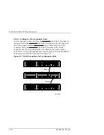
13. For BA370’s with 4+4 power configurations, go to the rear of the cabinet
and plug the black ac power cord from the BA370’s ac power controller into
the bottom PDU that already has a black power cord plugged into it. For
dual-redundancy units, plug the gray ac power cord from the BA370’s ac
power controller into the top PDU in the rear of the SW600 cabinet. Attach
ECB cables to the ECB and to the cache modules The top BA370 ECB is
located on the left-hand side of the ECB shelf. The bottom BA370 ECB is
located on the right-hand side of the ECB shelf.
14. Plug the PDU ac power cable(s) into the ac power source.
2.4
Cabling a Master Enclosure to an Expansion Enclosure(s)
NOTE
One DS-BNK37-1E cable kit is required for each
expansion unit.
2.4.1 Cabling Sequence
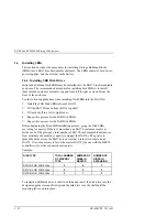
When adding an expansion BA370 unit, the following sequence is suggested.
1. Connect all six SE I/O cables between units..
2. After the SE I/O cables are attached, connect the EMU communication
cable.
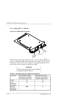
3. The last step is to set the PVA address.
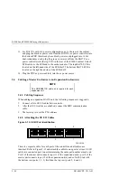
2.4.2 Attaching the SE I/O Cables
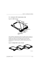
Figure 2–15 SE I/O Port Identification
CXO5819A
6
4
2
5
3
1
There is a separate cable for each port of the controller and all cables are
identical. Refer to Figure 2-15 and attach the cables to one port at a time. SE I/O
cables are connected port-to port maintaining the same port number at each end.
Port 1 of the master unit connects to port 1 of the expansion unit(s), port 2 of the
master unit connects to port 2 of the expansion unit(s), and so forth. Start with
the bottom row (ports 1, 3, 5) first then the top row (ports 2, 4, and 6).


