RA7000 and ESA10000 Storage Subsystems
2–30
EK–SMCPP–UG. A01
2.5
Connecting SCSI Bus Cables to the ESA10000
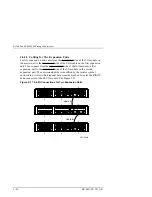
The internal SCSI bus cabling of two BA370’s within an ESA10000 cabinet as
well as the SCSI bus cabling between a master and expansion cabinet is shown in
Figure 2-22. The cabling scheme is to route the upper BA370’s I/O module
number 1’s left port to the lower BA370’s I/O module number 1’s right port.
Route the upper BA370’s I/O module number 2’s left port to the lower BA370’s
I/O module number 2’s right port. Follow this cabling scheme for cabling SCSI
bus cables in an ESA10000 that contains two BA370’s.
To expand the SCSI bus from a master cabinet to an expansion cabinet, route the
lower BA370’s SCSI bus cables from I/O module number 1’s left port to the
expansion cabinet’s I/O module number 1’s left port. Notice for expansion that
the cables run from the left port of the master cabinet to the left port of the
expansion port, just the opposite as for SCSI bus cabling between two BA370’s
that reside in the same cabinet. Again refer to Figure 2-22 for help in routing
SCSI bus cables.
The maximum bus length, including external cables (distance from the I/O
module terminator to the last terminator on the bus) is a function of the bus speed
and the number of devices. If the external cable is figured from SE I/O module to
SE I/O module with no devices installed in the middle, the cables may be
extended to 20 meters due to the isolation and re-timing circuitry of the SE I/O
module.


