RA7000 and ESA10000 Storage Subsystems
3–2
EK–SMCPP–UG. A01
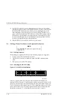
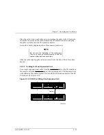
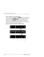
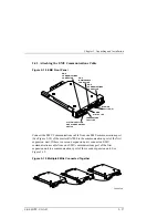
3.1.1 Connecting the EMU Communications Bus
In an expansion configuration you must establish communications between the
master EMU and each of the expansion EMUs. This is accomplished by
connecting a communications port on each EMU to a communications port on
another EMU. By establishing an EMU communications bus chain you ensure
that the master EMU can monitor and control all the enclosures in the UltraSCSI
subsystem.
DIGITAL recommends that you use a BN25G cable no longer than 4 m (13.1 ft.)
to connect the EMUs.
3.1.2 Setting the Temperature Sensors
There three temperature sensors in each UltraSCSI enclosure – two on the rear of
the backplane in the top middle and one mounted on the EMU module. You have
the option of setting the temperature at which an individual sensor reports an
over-temperature condition. You enter the desired temperature in degrees Celsius
(
°
C) within the range of 0ºC (32
°
F) through 49
°
C (120
°
F). See Table 3–3 for the
relationship between
°
C and
°
F (Fahrenheit).
The EMU sensor monitors the input, or ambient, air temperature while the two
enclosure sensors monitor the exhaust air temperature. The exhaust air
temperature can be higher than the ambient air temperature.
For each of the three sensors you have the option of selecting
SENSOR_n_SETPOINT = DEFAULT which establishes a set point of 35
°
C
(95
°
F). DIGITAL recommends that you use this setting for all three sensors.
Should the ambient temperature regularly be higher than 35
°
C (95
°
F), DIGITAL
recommends you select a temperature setting that ensures the continued
operation without endangering the components. Setting the temperature sensors
to the highest expected ambient temperature should ensure optimum operation.
CAUTION
To ensure proper operation, enter all temperatures
in °C. You cannot enter temperatures as fractions,
decimals, or in °F.

