Chapter 2. Unpacking and Installation
EK–SMCPP–UG. A01
2–19
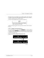
1. Position the mounting rails in the hole positions indicated by Tables 2-1 or
2-2. The upper and lower studs on the front of the mounting rail align with
the indicated holes in the front of the SW600 cabinet. The alignment tab
slides into a hole on the inner front vertical rail of the SW600 cabinet that
corresponds to the middle stud of the mounting rail. Attach the front of the
mounting rail to the front of the cabinet using 2 5/16” nuts on the top and
bottom studs of each rail and tighten. Refer to Figure 2-11. DO NOT attach
a 5/16” nut to the middle stud of the mounting rail. This is reserved for
locking the BA370 into the cabinet.
2. Slide four U-Nuts onto the rear vertical rails of the SW600 cabinet and over
the obvious holes that correspond to the rear mounting holes of the SW600
cabinet’s vertical rails, as shown in Figure 2-11. Attach the rear of the
mounting rails to the SW600 cabinet by inserting a 10/32” X 5/8” screw
through the holes in the mounting rails, through the rear vertical rails of the
SW600 and through the U-nuts. Because the front of the mounting rail is
already attached to the SW600 cabinet, the rear hole on the mounting rail
should automatically align with the proper hole on the rear vertical rail of
the SW600 cabinet. If you have doubts on proper rear hole alignment, count
the number of holes on the front of the SW600 cabinet up to the middle stud
of the mounting rail. The rear screw attachment hole should correspond to
the middle stud hole on the front of the mounting rail as well as to the
alignment tab hole.
Figure 2–11 Rail Installation into Cabinet
CXO5933A
U-nut
10/32"
screw
5/16"
nut
Stud
Middle
stud


