


Analog-to-Digital Converter/Brownout Detector
LH75400/01/10/11 (Preliminary) User’s Guide
23-6
6/25/03
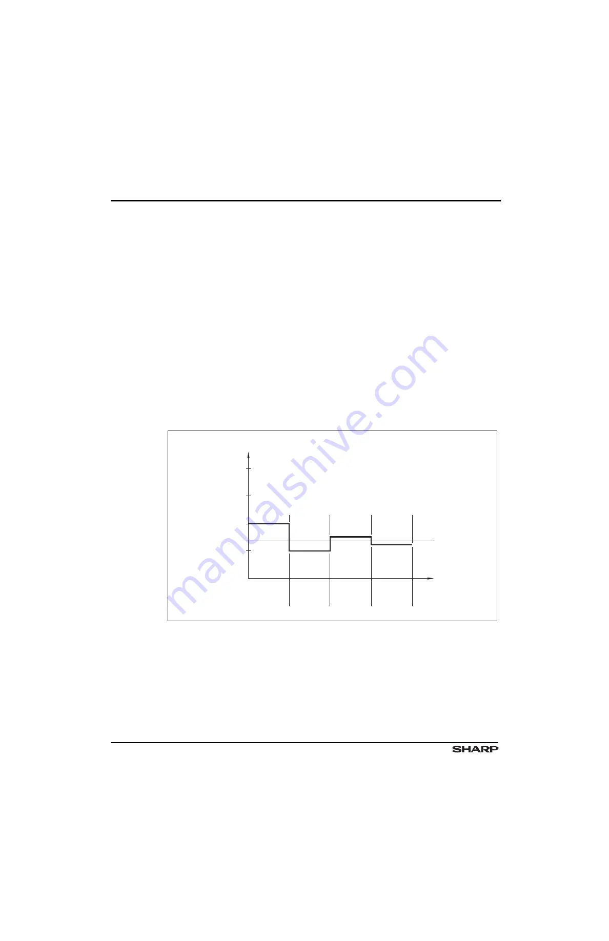
Figure 23-4 shows an example of a 4-bit conversion. In this figure, the y-axis and the bold
line show the DAC output voltage. In this example:
1.
The first comparison shows that VIN < VDAC. Consequently, bit [3] is set to 0. The
DAC is then set to 0100
2
and the second comparison is conducted.
2.
In the second comparison, VIN > VDAC, so bit [2] remains at 1. The DAC is then set
to 0110
2
and the third comparison is conducted.
3.
In the third comparison, bit [1] is set to 0 and the DAC is then set to 0101
2
for
the last comparison.
4.
In the final comparison, bit [0] remains at 1 because VIN
> VDAC.
Four comparison periods are necessary for a 4-bit ADC. Generally, an N-bit SAR ADC
requires N comparison periods and will not be ready for the next conversion until the cur-
rent conversion is completed. This explains why the ADC is power- and space-efficient.
Another feature of SAR ADCs is that power dissipation scales with the sample rate. By
comparison, flash or pipelined ADCs usually have constant power dissipation as opposed
to sample rate. This SAR ADC feature is especially useful in low-power applications or
applications where data acquisition is not continuous.
Figure 23-4. Example of a 4-bit SAR ADC Operation
VREF
3/4 VREF
1/2 VREF
1/4 VREF
BIT 3 = 0
(MSB)
BIT 2 = 1
BIT 1 = 0
BIT 0 = 1
(LSB)
VIN
TIME
VDAC
LH754xx-98