


6/17/03
22-1
Chapter 22
Controller Area Network
The Controller Area Network (CAN) block pertains to the LH75401 and LH75400
SoC devices only.
The CAN 2.0B Controller is an AMBA-compliant peripheral that connects as a slave to the
APB. The CAN Controller is located between the ARM processor and a CAN Transceiver, and
is accessed through the AMBA port. Figure 22-1 shows a block diagram of the CAN Controller.
CAN communications are performed serially, at a maximum frequency of 1MB/s, using
the TX (transmit) and RX (receive) lines. The RX and TX signals for data reception and
transmission provide the communications interface between the CAN Controller and the
CAN bus. All peripherals share the TX and RX lines and always see the common incoming
and outgoing data.
Data to be transmitted by the CAN Controller is placed in the Transmit Buffer and passed
to the Bit Processor, which channels the data onto the TX signal. Messages received by
the CAN Controller are filtered by the Acceptance Filter and placed in a 64-byte Receive
FIFO. The 64-byte Receive FIFO allows up to five Extended Frame Format (EFF) mes-
sages. Together, the Receive Buffer and Receive FIFO allow the CAN Controller to pro-
cess one message while a second message is being received. The bit rate is controlled
by the Bit Timing Logic block and is programmable to 1 Mbit/s.
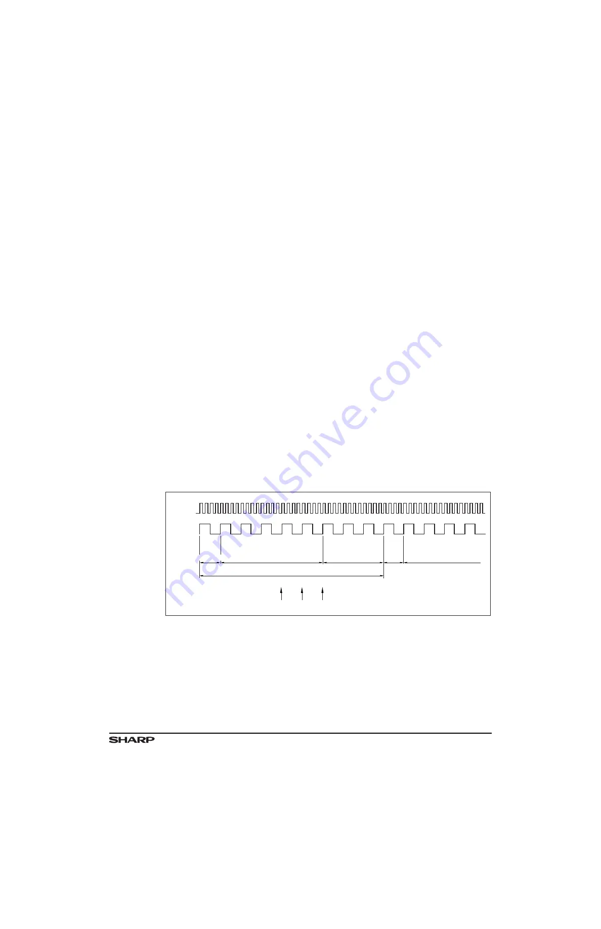
Figure 22-1. CAN Controller Block Diagram
SYSTEM
CLOCK
CAN
SYNC.
SEG.
SYNC.
SEG.
TSEG1
tSYNCSEG
tTSEG1
BIT PERIOD
SAMPLE POINT(s)
tTSEG2
TSEG2
TSEG1
LH754xx-26