4-21
4 Adjustment
4
12
13
14
ADJUSTMENT SCREW
15
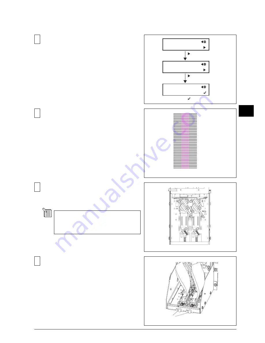
Select the [VERTICAL TEST PRINT] under the [HEAD
ADJUST] menu and press the [ENTER] key.
[VERTICAL ADJUSTMENT]
TEST PATTERN shown in the right figure will be
printed.
[ ]
SERVICE MENU
HEAD ADJUST
HEAD ADJUST
VERTICAL
VERTICAL
TEST PRINT
[ ]
[ ]
Loosen the 3 screws fixing the Head in order as shown
in the figure.
Loosen the screws fixing the Head for 1/2 turn.
If the screws are loosened too much,
adjustments could not be performed correctly.
Turn the ADJUSTMENT SCREW so that the lines of each
color in the test pattern will be straight.
*Reference*
Position of the printing moves 1 line by turning
the screw 30 degrees.
BK MG BK
!
Summary of Contents for SP-300
Page 128: ...2 Electrical Section 2 2 2 2 2 MAIN BOARD DIP SW DIP SW bit 1 bit 8 Always OFF ...
Page 134: ...2 Electrical Section 2 8 2 2 3 SERVO BOARD ...
Page 135: ...2 Electrical Section 2 9 2 ...
Page 140: ...2 Electrical Section 2 14 2 2 4 HEATER BOARD ...
Page 189: ...3 Replacement of Main Parts 3 42 3 9 Carry out the LINEAR ENCODER SETUP ...


