


3 Replacement of Main Parts
3-2
3
4
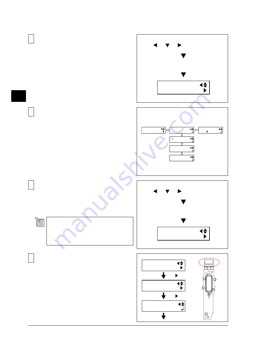
In [HEAD RANK] menu, select the Head No. of the
head that you are going to replace and input the HEAD
RANK written on the new head.
Input the HEAD RANK by selecting the digit with the
Left and Right keys, and changing the parameters with
the Up and Down keys.
Press the [ENTER] key to save the settings.
** The left Head is [HEAD 1].
HEAD RANK
HEAD 1
[ ]
[ ]
[ENTER]
SERVICE MENU
HEAD RANK
HEAD RANK 1
5CY2F2F (1/5)
HEAD RANK
3
Input the HEAD RANK of the head which is going to be
installed.
Turn on the SUB POWER SW while pressing the Left,
Right and Down keys to enter the SERVICE MODE.
[MENU] key
[ ], [ ], [ ] + POWER ON
MENU
SERVICE MENU
Make sure to input the HEAD RANK before
replacing the head, because the sticker which
the head rank is written on will be hidden
once the head is installed.
2
From the menu (NOT from the service menu), select
[INK CONTROL] > [PUMP UP], and remove the INK.
INK CONTROL
EMPTY MODE
INK CONTROL
PUMP UP
INK CONTROL
HEAD WASH
INK CONTROL
HEAD REPLACE
MENU
INK CONTROL
EMPTY MODE
STOP STOP
1
Turn on the SUB POWER SW while pressing the Left,
Right and Down keys to enter the SERVICE MODE.
[MENU] key
[ ], [ ], [ ] + POWER ON
MENU
SERVICE MENU
3-1 HEAD REPLACEMENT
Summary of Contents for SP-300
Page 128: ...2 Electrical Section 2 2 2 2 2 MAIN BOARD DIP SW DIP SW bit 1 bit 8 Always OFF ...
Page 134: ...2 Electrical Section 2 8 2 2 3 SERVO BOARD ...
Page 135: ...2 Electrical Section 2 9 2 ...
Page 140: ...2 Electrical Section 2 14 2 2 4 HEATER BOARD ...
Page 189: ...3 Replacement of Main Parts 3 42 3 9 Carry out the LINEAR ENCODER SETUP ...


