3 Replacement of Main Parts
3-31
3
15
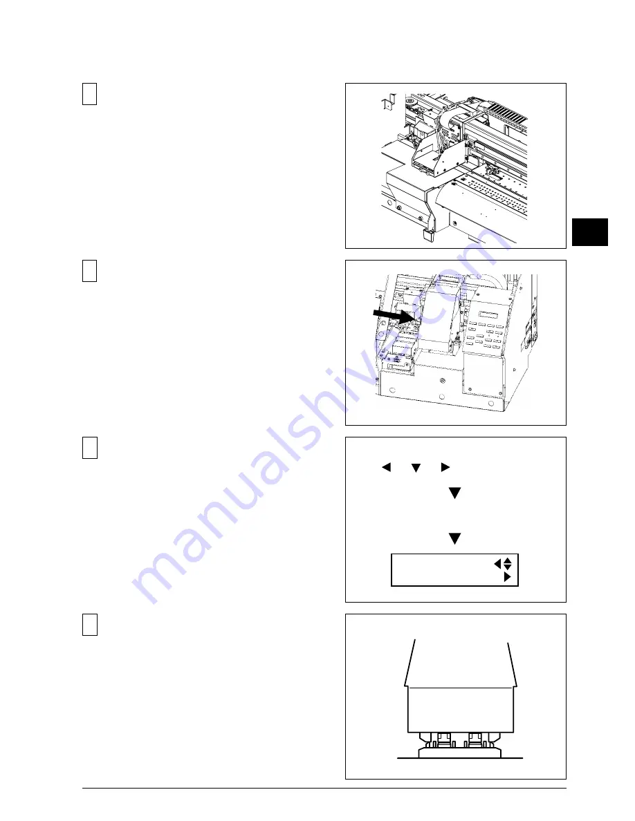
After turning on the main power, turn on the sub power
while pressing the Left, Right and Down keys to enter
the SERVICE MODE.
13
C o n n e c t 2 F L E X I B L E C A B L E s t o t h e P R I N T
CARRIAGE BOARD and put back the GUIDE PLATEs.
14
Move the HEAD CARRIAGE by hand to the lock
position.
16
Select [CAP&WIPER CTRL] > [CAP] > [UP], and press
the [ENTER] key to move up the capping unit 1 step.
Check that the GUIDEs at the two ends of the capping
unit align with the GUIDEs at the two ends of the head
carriage. Then press the [ENTER] key twice more to
cap the heads.
[MENU] key
[ ], [ ], [ ] + POWER ON
MENU
SERVICE MENU
Summary of Contents for SP-300
Page 128: ...2 Electrical Section 2 2 2 2 2 MAIN BOARD DIP SW DIP SW bit 1 bit 8 Always OFF ...
Page 134: ...2 Electrical Section 2 8 2 2 3 SERVO BOARD ...
Page 135: ...2 Electrical Section 2 9 2 ...
Page 140: ...2 Electrical Section 2 14 2 2 4 HEATER BOARD ...
Page 189: ...3 Replacement of Main Parts 3 42 3 9 Carry out the LINEAR ENCODER SETUP ...


