19
KS98+ I/O extensions with CANopen
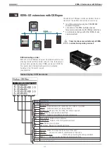
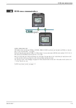
The additional CANopen interface completes the func-
tionality of the multifunction unit basic version by:
w
local I/O extensibility using the PMA RM 200
modular I/O system.
w
connection of the PMA multiple-channel
temperature controllers with CANopen interface
w
on-site data exchange with other KS98+ (cross
communication)
a
These functions are available only in KS98+
versions from operating version 5.
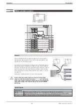
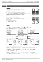
BUS terminating resistor
Both ends of the CANopen bus must be provided with a bus ter-
minating resistor at (first and last node). For this, the bus termi-
nating resistor provided in every KS98+ can be used. With the
SIL switch closed, the terminating resistor is activated.
As default, the SIL switch is open
(see opposite).
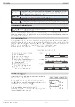
Status display : CAN bus status
9499 040 50611
KS98+ I/O extensions with CANopen
117
Value
Signification
1
...
42
Node number
NC
NoCheck: Node existence not checked so far / node not provided
Ck
Check:
Node existence just being checked.
NR
NoResponse: No reply from this node, but node is required.
OK
Ready:Node has replied and is identified.
ES
EMStart: Node has provided an emergency message.
NA
NotAvailable: Node status is unknown.
PO
PreOperation: Node is in the PreOperational status.
Er
Error: Node is in error status.
Op
Operational: Node is in Operational status.
NU
NotUsed: Node is not required by an own lib function.
Wa
Waiting:
Lib function waits for identification of this node.
Pa
Parameter setting:
Lib function just setting the node parameters.
OK
Ready:
Lib function has finished the parameter setting.
String detemined node name
+24 V
OUT
+24 V
OUT
Error
1
Error
4
Error
2
Error
3
+24V
OUT
+24V
OUT
I
in1
0..20
mA
I
in2
0..20
mA
I
in4
0..20
mA
I
in3
0..20
mA
A-IN/I
RM 220-0
Error
1
Error
4
Error
2
Error
3
NC
NC
NC
NC
I
in1
0..20
mA
I
in2
0..20
mA
I
in4
0..20
mA
I
in3
0..20
mA
A-IN/I
RM 221-0
+24 V
OUT
+24 V
OUT
Error
1
Error
4
Error
2
Error
3
+24V
OUT
+24V
OUT
I
in1
0..20
mA
I
in2
0..20
mA
U
in4
-10..10
V
U
in3
-10..10
V
A-IN/I,U
RM 222-2
Error
1
Error
4
Error
2
Error
3
+
-
+
-
4
3
+
-
+
-
2
1
A-IN/TEMP
RM 224-1
GND RxD TxD
Alarm
Receive
Power
Transmit
RTS
B/P
A/N
GND
GND
+5V
OUT
+24V
IN
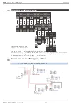
P-DP-CPU
RM 202
+24 V
OUT
+24 V
OUT
Error
1
Error
4
Error
2
Error
3
+24V
OUT
+24V
OUT
I
in1
0..20
mA
I
in2
0..20
mA
I
in4
0..20
mA
I
in3
0..20
mA
A-IN/I
RM 220-0
Error
1
Error
4
Error
2
Error
3
NC
NC
NC
NC
I
in1
0..20
mA
I
in2
0..20
mA
I
in4
0..20
mA
I
in3
0..20
mA
A-IN/I
RM 221-0
GND RxD TxD
Alarm
Receive
Power
Transmit
RTS
B/P
A/N
GND
GND
+5V
OUT
+24V
IN
P-DP-CPU
RM 202
open
Summary of Contents for KS 98
Page 8: ...Description 9499 040 50611 Construction 8...
Page 10: ...Important technical data 9499 040 50611 Further external in and outputs 10...
Page 12: ...Versions 9499 040 50611 I O modules for units with modular option c basic card 12...
Page 14: ...Front view 9499 040 50611 14...
Page 16: ...Mounting 9499 040 50611 16...
Page 26: ...Maintenance 9499 040 50611 Further information 26...
Page 36: ...Scaling and calculating functions 9499 040 50611 LG10 10s logarithm 36...
Page 74: ...Signal converters 9499 040 50611 MEAN mean value formation 74...
Page 128: ...KS98 I O extensions with CANopen 9499 040 50611 RM_DMS strain gauge module 128...
Page 132: ...CSEND Send mod blockno s 21 23 25 27 No 57 132...
Page 140: ...Description of KS98 CAN bus extension 9499 040 50611 140...
Page 202: ...Controller 9499 040 50611 Process value calculation 202...

