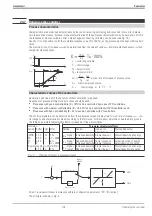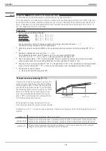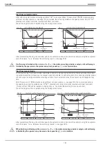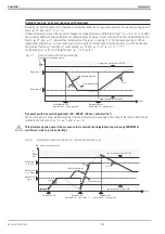
Self-tuning procedure with heating:
(2-point, 3-point stepping, continuous controller)
After reaching ‘Process in rest’, the process is stimulated by means of an output step change and the process response
is used to determine Tu1 and Vmax1 at the step response reversal point, if possible.
Self-tuning procedure with heating and cooling processes:
(3-point / split-range controller)
Self-tuning starts as with a “heating” process. After self-tuning end, the controller settings based on the calculated pa-
rameters are made. This is followed by line-out at the pre-defined set-point, until PiR is reached again. Subsequently,
a step to cooling is made to determine the “cooling” parameters, in order to determine Tu2 and Vmax2 using the step
response. Based on these characteristics, the controller settings for the cooling process are made. When cancelling the
cooling attempt, the parameters for “heating” are also taken over for cooling. No error message (
Ada_Err
) is out-
put.
g
With 3-point stepping controllers, the motor actuator is closed first after starting and opening to
YOptm
will occur only then. This calibration procedure (
Stat: Abgl.
) is not shown in the figures.
g
For maintaining a safe process condition, monitoring for an exceeded set-point is done continuously.
a
During self-tuning, the control’ function is switched off! I.e.: Ypid is within the limits of Ymin and Ymax.
a
With
Off controllers, self-tuning is using the
function, i.e.Y2 = 0.
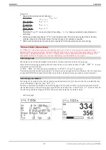
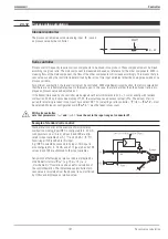
Controlled adaptation
For defined applications, adaptation of the control parameter set to the current process condition is purposeful. For this,
the Contr+ is provided with 6 control parameter sets, which can be selected via analog input
ParNo
.
9499 040 50611
Controller
183
Self-tuning
r
controller adaptation to the process
t
t
Y
100%
0%
-100%
X
W
60s
60s
PiR
PiR
Start
Adaption
Optimisation
heazing
finished
Optimisation
cooling
finished
Start
+
YOptm
dYopt
Off/Ok
PIR_H
Step
Off/Ok
PIR_K
Step
Fig.: 10
Self-tuning with
heating and cooling
/ /
Summary of Contents for KS 98
Page 8: ...Description 9499 040 50611 Construction 8...
Page 10: ...Important technical data 9499 040 50611 Further external in and outputs 10...
Page 12: ...Versions 9499 040 50611 I O modules for units with modular option c basic card 12...
Page 14: ...Front view 9499 040 50611 14...
Page 16: ...Mounting 9499 040 50611 16...
Page 26: ...Maintenance 9499 040 50611 Further information 26...
Page 36: ...Scaling and calculating functions 9499 040 50611 LG10 10s logarithm 36...
Page 74: ...Signal converters 9499 040 50611 MEAN mean value formation 74...
Page 128: ...KS98 I O extensions with CANopen 9499 040 50611 RM_DMS strain gauge module 128...
Page 132: ...CSEND Send mod blockno s 21 23 25 27 No 57 132...
Page 140: ...Description of KS98 CAN bus extension 9499 040 50611 140...
Page 202: ...Controller 9499 040 50611 Process value calculation 202...


