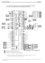
6.5
Analog inputs (
r
connecting diagram)
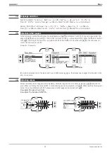
Thermocouples (a)
No lead resistance adjustment is necessary.
Internal temperature compensation
: the compensating lead must be taken up to the instrument terminals.
In
AINP1
STK = int.TC
must be configured.
External temperature compensation
: use a separate cold-junction reference with fixed reference temperature. The com-
pensating lead is taken up to the cold-junction reference, whilst the lead between cold-junction reference and instru-
ment can be of copper.
In
AINP1
STK = ext.TC
and with
TKref =
the reference temperature must be configured.
Resistance thermometer Pt 100 in 3-wire connection (b)
No lead resistance adjustment is necessary, provided that RL1 = RL2.
Resistance thermometer Pt 100 in 2-wire connection (c)
Lead resistance adjustment is necessary: make Ra equal to RL1 + RL2.
Two resistance thermometers Pt100 in difference connection (d)
Compensating the lead resistances: proceed as described
r
24 .
Resistance transducer (e)
Calibrating the measurement: proceed as described
r
24 .
Standard voltage signals 0/2...10V (g)
Input resistance:
?
100 k
[
, Configure scaling and digits behind the decimal
point. INP5 is a difference input, the reference potential of which is connected
to terminal A9. With voltage input, A6 must always be connected with A9.
Standard current signals 0/4...20 mA (f)
Input resistance: configure 50
[
, scaling and digits behind the decimal point.
Supply voltage -50...1300mV DC
(only INP3 on instruments with order no. 9407-9xx-x2xx1):
With type =0...20mA, the input is designed for -50...1300 mV. For using the INP3 output with this scaling, set x0 to -50
and x100 to 1300.
a
Inputs INP1 / INP6 are interconnected. This must be taken into account, if both inputs must be used for standard
current signals. If necesary, a galvanic isolation must be used.
9499 040 50611
Electrical connections
19
Analog inputs (
r
connecting diagram)
Summary of Contents for KS 98
Page 8: ...Description 9499 040 50611 Construction 8...
Page 10: ...Important technical data 9499 040 50611 Further external in and outputs 10...
Page 12: ...Versions 9499 040 50611 I O modules for units with modular option c basic card 12...
Page 14: ...Front view 9499 040 50611 14...
Page 16: ...Mounting 9499 040 50611 16...
Page 26: ...Maintenance 9499 040 50611 Further information 26...
Page 36: ...Scaling and calculating functions 9499 040 50611 LG10 10s logarithm 36...
Page 74: ...Signal converters 9499 040 50611 MEAN mean value formation 74...
Page 128: ...KS98 I O extensions with CANopen 9499 040 50611 RM_DMS strain gauge module 128...
Page 132: ...CSEND Send mod blockno s 21 23 25 27 No 57 132...
Page 140: ...Description of KS98 CAN bus extension 9499 040 50611 140...
Page 202: ...Controller 9499 040 50611 Process value calculation 202...

