7.7
Calibrating
Select (
ID
) and open (
M
) Miscellaneous
r
Calibration
. Select the bottommost line by pressing
I
(in-
verted display, e.g.
Quit
). Then continue as follows:
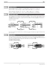
Transducer input (INP1 or INP6)
2 Resistance thermometer in difference (INP1)
Calibrating the transducer start and end:
Calibrating the lead resistance effect:
Ü
Set the transducer to start (
r
section operating modes)
Ü
Short-circuit the thermometer in the connecting
head
*
Press
M
r
Quit
blinks
*
*
Press
M
r
Quit
blinks
*
Ö
Press
I
r
Set 0%
blinks
Ö
Press
I
r
Set Dif
blinks
ä
Wait until the input has settled (min. 6 s)
ä
Wait until the input has settled (min. 6 s)
#
Press
M
r
0% done
is displayed
#
Press
M
r
Cal done
is displayed
<
Set the transducer to end (
r
Section Operating modes)
>
Press
M
r
0% done
blinks
y
Press
I
3x
r
Set 100%
blinks
x
Wait until the input has settled (min. 6 s)
©
Press
M
r
100% done
is displayed
Calibration is finished
.
For leaving the calibration press
D
until nothing is
marked and press
M
.
Lead resistance adjustment is finished.
Remove both short circuits. For leaving the calibration
press
D
until nothing is marked and press
M
.
*
If another word blinks, key
I
or
D
must be pressed, until the required word blinks.
7.8
Operating modes
q
Online/Offline
For configuration changing, set the unit to ‘Offline’ and back to ‘Online’
(
Miscellaneous
,
Online/Offline
).
q
Manual mode/automatic mode
When using controllers, it may happen that automatic or manual mode is requested by
several units. The controller leaves the manual mode, when
all
control signals request
automatic operation.
Example
: INP6 is provided for transducers and connected accordingly (position feedback).
When this input is calibrated, the controller can be switched to manual mode on the
calibrating page (by means of
H
,
Man
. is displayed on the bottom left). Now, pressing
I
and
M
to mark line
Y
and pressing
I
/
D
to drive the actuator to its limits is possible. After
calibration, the manual mode must be switched off again
on this page
. (press
H
).
Menu
9499 040 50611
Calibrating
24
Summary of Contents for KS 98
Page 8: ...Description 9499 040 50611 Construction 8...
Page 10: ...Important technical data 9499 040 50611 Further external in and outputs 10...
Page 12: ...Versions 9499 040 50611 I O modules for units with modular option c basic card 12...
Page 14: ...Front view 9499 040 50611 14...
Page 16: ...Mounting 9499 040 50611 16...
Page 26: ...Maintenance 9499 040 50611 Further information 26...
Page 36: ...Scaling and calculating functions 9499 040 50611 LG10 10s logarithm 36...
Page 74: ...Signal converters 9499 040 50611 MEAN mean value formation 74...
Page 128: ...KS98 I O extensions with CANopen 9499 040 50611 RM_DMS strain gauge module 128...
Page 132: ...CSEND Send mod blockno s 21 23 25 27 No 57 132...
Page 140: ...Description of KS98 CAN bus extension 9499 040 50611 140...
Page 202: ...Controller 9499 040 50611 Process value calculation 202...


