14.4
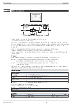
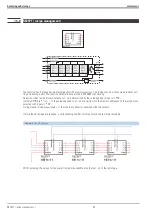
DELA1 ( delay time )
If the clock input is not wired, the function calculates y1(t) = x1 (t-n
•
ts).
(
ts
= sampling interval,
Delay
= delay factor n)
Unless clock input clock is wired, the following is applicable: input variable
x1
is output with a delay by n times the
amount of adjusted sampling interval ts ( phase shift by
n ts
×
). The effective delay time corresponds to integer multiples
of the selected time group (sampling interval
ts
100/200/400/800 ms). The delay time range covers n= 0 to 255 (
0
255
.....
×
ts
)
With clock input clock wired, DELA1 acts like a shift register with a length of max. 255=Parameter
delay
. This register can be switched on by one step by an external event
preset
.
Switching on is only with a positive flank ( transition from 0
r
1) at the clock input plus the adjusted delay factor (pa-
rameter
delay
).
Example:
With
delay
=
4 change-over at output y is only after 4 flank changes from 0
r
1 at input cloc
k
Preset
: The output provides the value applied to Preset. After (n+1) positive flanks at clock or
(n+1) sampling cycles t
S
(if clock isn't wired), the first input value x1 appears at y1.
reset
: The output provides value 0. After a positive flank at clock, value zero still is provided
for the sampling interval ts.
The function has a ‘memory’. This means: after power-on, it continues operating with values y1, z1 and z2, which ex-
isted at power-on, provided that the RAM data are still unchanged.
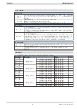
Inputs/outputs
Digital inputs
clock
= 0->1 clock for delaying
preset
= 1 The preset value is taken to the output
reset
= 1 Output
y1
is set to zero
Analog inputs
x1
Input variable to be delayed
Preset
Value output without delay by
preset
= 1
With several simultaneous control commands:
reset
= 1 has priority over
preset
and
stop
preset
= 1 has priority over
stop
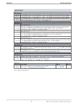
Analog output
y1
Delayed output variable
Parameter:
Parameter
Description
Range
Default
Delay
Delay factor n
0/1/.....255
0
Time functions
9499 040 50611
DELA1 ( delay time )
80
Summary of Contents for KS 98
Page 8: ...Description 9499 040 50611 Construction 8...
Page 10: ...Important technical data 9499 040 50611 Further external in and outputs 10...
Page 12: ...Versions 9499 040 50611 I O modules for units with modular option c basic card 12...
Page 14: ...Front view 9499 040 50611 14...
Page 16: ...Mounting 9499 040 50611 16...
Page 26: ...Maintenance 9499 040 50611 Further information 26...
Page 36: ...Scaling and calculating functions 9499 040 50611 LG10 10s logarithm 36...
Page 74: ...Signal converters 9499 040 50611 MEAN mean value formation 74...
Page 128: ...KS98 I O extensions with CANopen 9499 040 50611 RM_DMS strain gauge module 128...
Page 132: ...CSEND Send mod blockno s 21 23 25 27 No 57 132...
Page 140: ...Description of KS98 CAN bus extension 9499 040 50611 140...
Page 202: ...Controller 9499 040 50611 Process value calculation 202...


