– 77 –
Chapter 5 Basic Operations — DSK (Downstream key)
DSK transition
Operating in the DSK operation area
r
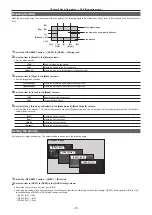
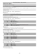
Operating the <DSK1 TRNS> to <DSK4 TRNS> buttons
Press the <DSK1 TRNS> to <DSK4 TRNS> buttons in the transition area to execute a transition automatically with the transition time of respective keys
set on the menu.
The <DSK1 TRNS> to <DSK4 TRNS> buttons flicker during key in, and light when the transition is complete. If the <DSK1 TRNS> to <DSK4 TRNS>
buttons are pressed while key in is complete, transition of the key image (key out) is executed.
The <DSK1 TRNS> to <DSK4 TRNS> buttons light during key out, and go off when the transition is complete. If the <DSK1 TRNS> to <DSK4 TRNS>
buttons are pressed during the transition, the transition direction is reversed.
r
Operating the <DSK1 ON> to <DSK4 ON> buttons
Press the <DSK1 ON> to <DSK4 ON> buttons to turn on/off respective DSK with the cut transition.
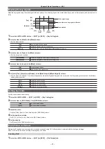
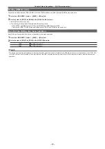
Setting the DSK transition mode
Transition mode and transition time can be set separately for key in and key out.
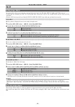
1
Select the <DSK MISC> button
→
[DSK1] to [DSK4]
→
[Transition] tab.
2
Select an item in [Transition] in the [In Type]/[Out Type] column.
f
The transition mode available is only [MIX].
[Off]
Disables the transition mode of key in or key out.
[On]
Enables the transition mode of key in or key out.
3
Set [Time] in the [In Type]/[Out Type] column.
f
Set the transition time.
4
Select an item in [In=Out] in the [Out Type] column.
[Off]
Sets the [In Type] column and the [Out Type] column separately.
[On]
The [In Type] column setting becomes the same as the [Out Type] column setting.
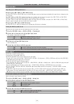
DSK output
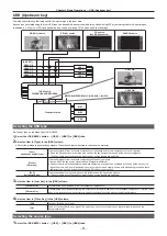
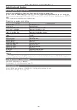
The DSK block outputs the following signals.
For details, refer to “System Menu” (page 140).
f
DSKPGM1, DSKPGM2: Outputs program signals of DSK compositions.
Select the <SYS> button on the top menu
→
[MAIN FRAME]
→
[DSK] tab
→
[Config] column
→
[DSK1] to [DSK4] and set them to either [DSKPGM1]
or [DSKPGM2] to assign the signal to one of the outputs.
f
DSKPVW1, DSKPVW2: Outputs DSK preview signals.
Follow the setting of the <SYS> button on the top menu
→
[MAIN FRAME]
→
[DSK] tab
→
[Config] column
→
[DSK1] to [DSK4], and assign the signal
to either DSKPVW1 or DSKPVW2 line.
Keyers set to [Off] using the <SYS> button on the top menu
→
[MAIN FRAME]
→
[DSK] tab
→
[DSK PVW] column are not combined.
f
DSK1CLN, DSK2CLN, DSK3CLN, DSK4CLN: Outputs clean signal before adding key effects from each keyer. It can also be switched to preview
image of each DSK.
f
SEL KEYPVW: Outputs the preview for the key for pressed <KEY1> to <KEY4> buttons in the KEY operation area of each ME, and <DSK1> to
<DSK4> buttons. The image combined with the key where the <SYS> button on the top menu
→
[MAIN FRAME]
→
[Sel KeyPVW] tab
→
[ME1]/
[ME2]/[DSK] column is set to [On] is output. If the button for the key set to [Off] is selected, the image is output without the key combined.
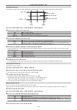
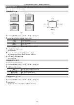
Adjusting the luminance key/linear key
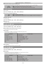
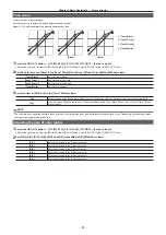
Adjust the luminance key and linear key definition.
1
Select the <DSK MISC> button
→
[DSK1] to [DSK4]
→
[Setting] tab.
2
Set [Clip], [Gain], and [Density] in the [DSK Adjust] column.
[Clip]
Sets the reference level for creating key signals.
[Gain]
Sets the key amplitude.
[Density]
Sets the key density.
3
Select an item in [Invert] in the [DSK Adjust] column.
[Off]
Does not invert the key signals generated internally.
[On]
Inverts the key signals generated internally.
Summary of Contents for AV-HS60C1E
Page 5: ...Please read this chapter and check the accessories before use Chapter 1 Overview ...
Page 52: ...This chapter describes menu operations Chapter 5 Basic Operations ...
Page 162: ...This chapter describes the difference with the Standard mode Chapter 9 3G mode 4K mode ...
Page 168: ...This chapter describes the terminals and signals of the unit Chapter 10 External Interfaces ...
Page 184: ...This chapter describes the setting menu table and terms Chapter 12 Appendix ...
Page 206: ...Web Site http www panasonic com Panasonic Corporation 2014 ...

