– 170 –
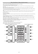
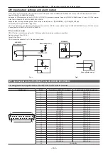
Chapter 10 External Interfaces — GPI input/output settings and alarm output
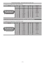
Pin assignments and signal names of the <GPI IN> terminal
Outside view
Pin No.
Signal name
Pin No.
Signal name
1
14
25
13
1
GPI IN-1
14
GPI IN-13
2
GPI IN-2
15
GPI IN-14
3
GPI IN-3
16
GPI IN-15
4
GPI IN-4
17
GPI IN-16
5
GPI IN-5
18
GPI IN-17
6
GPI IN-6
19
GPI IN-18
7
GPI IN-7
20
COM (GND)
8
GPI IN-8
21
ALARM OUT
9
COM (GND)
22
NC
10
GPI IN-9
23
NC
11
GPI IN-10
24
NC
12
GPI IN-11
25
COM (GND)
13
GPI IN-12
GPI input/output ports of the Control Panel AV‑HS60C1/AV‑HS60C2/AV‑HS60C4
Pin assignments and signal names of the <GPI I/O> terminal
Outside view
Pin No.
Signal name
Pin No.
Signal name
1
14
25
13
1
GPI IN-1
14
GPI OUT-5
2
GPI IN-2
15
GPI OUT-6
3
GPI IN-3
16
GPI OUT-7
4
GPI IN-4
17
GPI OUT-8
5
GPI IN-5
18
GPI OUT-9
6
GPI IN-6
19
GPI OUT-10
7
GPI IN-7
20
COM (GND)
8
GPI IN-8
21
ALARM OUT
9
COM (GND)
22
NC
10
GPI OUT-1
23
NC
11
GPI OUT-2
24
NC
12
GPI OUT-3
25
COM (GND)
13
GPI OUT-4
Summary of Contents for AV-HS60C1E
Page 5: ...Please read this chapter and check the accessories before use Chapter 1 Overview ...
Page 52: ...This chapter describes menu operations Chapter 5 Basic Operations ...
Page 162: ...This chapter describes the difference with the Standard mode Chapter 9 3G mode 4K mode ...
Page 168: ...This chapter describes the terminals and signals of the unit Chapter 10 External Interfaces ...
Page 184: ...This chapter describes the setting menu table and terms Chapter 12 Appendix ...
Page 206: ...Web Site http www panasonic com Panasonic Corporation 2014 ...

