– 153 –
Chapter 8 System Menu — Setting the external connection
Setting the external connection
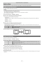
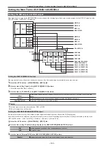
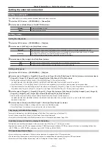
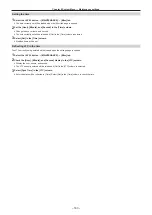
Setting a serial port
The <COM4 (M/S)> port can be switched between master and slave connection.
1
Select the <SYS> button
→
[PERIPHERAL]
→
[General] tab.
2
Select an item in [Master/Slave] in the [MF COM4] column.
[Master]
A master connection is used.
[Slave]
A slave connection is used.
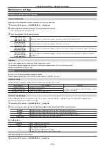
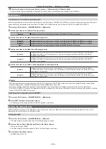
Setting a tally
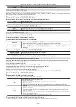
Setting the tally mode
1
Select the <SYS> button
→
[PERIPHERAL]
→
[Tally] tab.
2
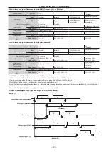
Select an item in [MV Tally] in the [Tally Mode] column.
[Internal]
The tally of each sub-screen of the MultiView display is updated according to the tally generated by the unit.
[External]
The tally of each sub-screen of the MultiView display is not updated by tally generated by the unit and is updated
according to the information from external devices connected to the unit.
The tally control from external devices is supported by the plug-in software.
3
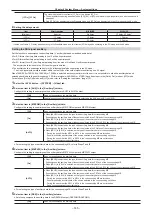
Select an item in [Key Judge] in the [Tally Mode] column.
[ON]
On/off of the tally is determined by corresponding source is included in the valid screen.
[OFF]
On/off of the tally is determined from the transition amount or on/off of the key.
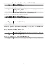
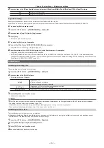
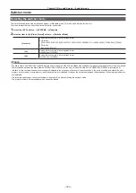
Setting a tally group
1
Select the <SYS> button
→
[PERIPHERAL]
→
[Tally] tab.
2
Select an item in [Target A], [
+
Target B], [
+
Target C], and [
+
Target D] of the [Tally Group1‑1 (On‑Air)] column, and select an item in
[
+
Target E], [
+
Target F], [
+
Target G], and [
+
Target H] of the [Tally Group1‑2 (On‑Air)] column.
f
Set the reference output for [Tally Group1-1 (On-Air)]/[Tally Group1-2 (On-Air)] (on-air tally).
Off, ME1PGM, ME1CLN, ME2PGM, ME2CLN, DSKPGM1, DSKPGM2, DSK1CLN to DSK4CLN, AUX1 to AUX16
f
Since [Tally Group1‑1 (On‑Air)]/[Tally Group1‑2 (On‑Air)] is used exclusively for on‑air tally, a preview output cannot be specified.
f
Tally information of sources that configure any of the outputs set in [Target A], [
+
Target B], [
+
Target C], and [
+
Target D] of the [Tally Group1-1 (On-
Air)] column and [
+
Target E], [
+
Target F], [
+
Target G], and [
+
Target H] of the [Tally Group1-2 (On-Air)] column is generated.
3
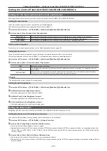
Select an item in [Target A], [
+
Target B], [
+
Target C], [
+
Target D] of columns [Tally Group2‑1] to [Tally Group4‑1], and [
+
Target E],
[
+
Target F], [
+
Target G], and [
+
Target H] of columns [Tally Group2‑2] to [Tally Group4‑2].
f
Set the reference output for [Tally Group2-1]/[Tally Group2-2] to [Tally Group4-1]/[Tally Group4-2].
Off, ME1PGM, ME1CLN, ME2PGM, ME2CLN, DSKPGM1, DSKPGM2, DSK1CLN to DSK4CLN, AUX1 to AUX16, ME1PVW, ME2PVW,
DSKPVW1, DSKPVW2
4
Select an item in [Color] in the [Tally Group1‑1 (On‑Air)] to [Tally Group4‑1] columns.
f
Select [Red], [Green], [Yellow], or [Orange] for the color of the MultiView display.
f
Since [Tally Group1] is exclusively for on‑air tally, the color is fixed to [Red].
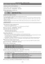
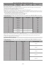
Tally display of the MultiView display
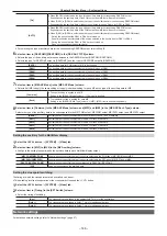
The target of tally display of the MultiView display is [Tally Box], [Tally Label L], and [Tally Label R].
For each of those areas, [Tally Group1] to [Tally Group4] are set and displayed.
f
For details on the tally display of the MultiView display, refer to “Setting the tally display” (page 128).
High tally display and bus tally display of the button
The High tally and bus tally are displayed for the next button from [Tally Group1-1 (On-Air)] (on-air tally).
f
Applicable buttons are the KEY bus crosspoint buttons, PGM/A bus crosspoint buttons, PST/B bus crosspoint buttons, corresponding buttons from
<KEY1 TRNS> to <KEY4 TRNS>, and buttons from <DSK1 TRNS> to <DSK4 TRNS>.
GPI input/output tally settings
f
For each tally group, a maximum of 48 source tally outputs can be assigned to the GPI output terminal.
f
The functions can be assigned in each tally group and can be enabled/disabled externally through the GPI input terminal.
f
For details on GPI input/output tally settings, refer to “Setting the GPI input/output” (page 154).
Summary of Contents for AV-HS60C1E
Page 5: ...Please read this chapter and check the accessories before use Chapter 1 Overview ...
Page 52: ...This chapter describes menu operations Chapter 5 Basic Operations ...
Page 162: ...This chapter describes the difference with the Standard mode Chapter 9 3G mode 4K mode ...
Page 168: ...This chapter describes the terminals and signals of the unit Chapter 10 External Interfaces ...
Page 184: ...This chapter describes the setting menu table and terms Chapter 12 Appendix ...
Page 206: ...Web Site http www panasonic com Panasonic Corporation 2014 ...


