– 13 –
Chapter 2 Installation and Connection (To installation personnel) — Installation (To installation personnel)
f
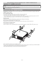
Do not install the unit in a manner in which the unit or cables can be easily damaged.
f
Avoid installing the unit where it will be exposed to direct sunlight or to the hot air that is blown out from other products.
f
Installing the unit in a very humid, dusty, or vibration-prone location may cause malfunction.
Installing the Control Panel AV‑HS60C1/AV‑HS60C2/AV‑HS60C4
When installing or connecting the unit, be sure to ask your dealer. When you want to add the redundant power supply on the Control Panel
AV‑HS60C1, consult your dealer.
r
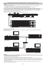
Connecting the power supply
f
Connect the <SIGNAL GND> terminal on the rear panel of the unit to the ground of the system.
f
Use the Control Panel AV-HS60C2/AV-HS60C4 with both the power supply 1 and the power supply 2.
An alarm is displayed when there is no AC power input to the power supply 1 and the power supply 2 or when the power switch is set to <OFF>.
(An alarm will not be displayed on the Control Panel AV-HS60C1, because it has only the power supply 1.)
r
Handle carefully.
f
Dropping the unit or subjecting it to strong impact or vibration may cause trouble and/or malfunctioning.
r
Do not allow any foreign objects to enter inside the unit.
f
Allowing water, metal items, scraps of food or other foreign objects inside the unit may cause a fire and/or electric shocks.
r
Choosing the best installation location
f
This unit is a device for indoor use only.
f
Install the unit on a sufficiently strong, stable, and level surface for use.
f
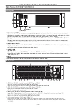
Secure a space surrounding the ventilation holes on the front panel of the power supply unit and on the rear panel of the Control Panel AV-HS60C1/
AV-HS60C2/AV-HS60C4 so that air circulation is not impeded.
In particular, ensure sufficient space between ventilation and wiring when using mounted in a panel or table.
f
Avoid installing the unit where it will be exposed to direct sunlight or to the hot air that is blown out from other products.
f
Installing the unit in a very humid, dusty or vibration-prone location may cause malfunction.
Installing the Menu Panel AV‑HS60C3
Attach the panel using 4 mounting holes (M4 screw
×
4, 75 mm (2-15/16 inches) pitch) on the rear panel of the Menu Panel AV-HS60C3.
For details, refer to “Dimensions of the Menu Panel AV-HS60C3” (page 177).
Attaching the Storage Module AV‑HS60D1 (SSD)
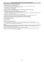
If attached inside the Main Frame AV-HS60U1/AV-HS60U2, register memories of Still and Clip, and project data can be saved in the Main Frame
AV-HS60U1/AV-HS60U2.
For details, refer to the “Installation Guide” of the Storage Module AV-HS60D1 (optional).
@
@
NOTE
t
When attaching or removing the module, be sure to ask your dealer.
t
Before attaching or removing the module, turn off the power, and disconnect the power plug.
t
Before coming into physical contact with the Storage Module AV-HS60D1 (optional), touch a grounded metal object with your hand to discharge the
static electricity in your body. A safe way to proceed is to wear an anti-static wrist strap. Touching the option board with static still in your body may
cause malfunction.
t
Do not drop the Storage Module AV-HS60D1 (optional) or subject it to strong impact or vibration.
t
When attaching or removing the Storage Module AV-HS60D1 (optional), take care not to hurt yourself on the edges or metal parts of the Main Frame
AV-HS60U1/AV-HS60U2.
Summary of Contents for AV-HS60C1E
Page 5: ...Please read this chapter and check the accessories before use Chapter 1 Overview ...
Page 52: ...This chapter describes menu operations Chapter 5 Basic Operations ...
Page 162: ...This chapter describes the difference with the Standard mode Chapter 9 3G mode 4K mode ...
Page 168: ...This chapter describes the terminals and signals of the unit Chapter 10 External Interfaces ...
Page 184: ...This chapter describes the setting menu table and terms Chapter 12 Appendix ...
Page 206: ...Web Site http www panasonic com Panasonic Corporation 2014 ...

