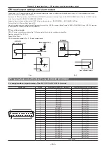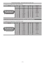
– 155 –
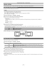
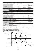
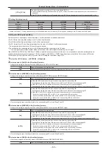
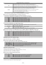
Chapter 8 System Menu — Setting the external connection
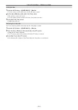
2
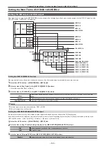
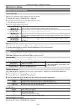
Select [ID] and select an item.
f
Select [Mainframe], [MainPanel], [SubPanel1], or [SubPanel2] as the setting target.
3
Select the port where you want to assign a function from the port list in the left column.
f
Select [Select] to filter the port list in the left column. Select a color from [All], [GPI Out1‑6], [GPI Out7‑12], [GPI Out13‑18], [GPI Out19‑24], [GPI
Out25-30], [GPI Out31-36], [GPI Out37-42], and [GPI Out43-48].
4
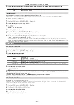
Select the function to assign from the function list in the right column.
f
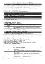
Select [Type] to select the type of output signal from the function list in the right line.
- [LowEdge]: Falling edge
- [HighEdge]: Rising edge
- [LowLevel]: Low level
- [HighLevel]: High level
f
Select [Group Select] to switch the group of the function list in the right column.
For details, refer to “GPI output function list” (page 155).
f
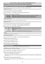
For tally output assignment, select [Tally Select] to set the tally group.
f
For details, refer to “Tally output function list” (page 155).
5
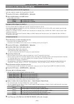
Select [Assign].
f
The function is assigned to the button selected in the step
.
f
Select [Test Fire] to test the signal output operation of the set GPI port. The pulse of Low level is output for approximately 0.05 seconds.
r
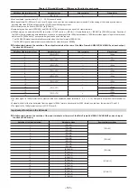
GPI output function list
Describes about when [ME1], [ME2], [DSK], [USK], or [OTHER] is selected in [Group Select].
[Group Select]
Signal name
Description
[Type]
[ME1], [ME2]
KEY1 ON to KEY4 ON
Key on
[LowLevel] or [HighLevel]
KEY1 CUT to KEY4 CUT
Cut transition of a key was executed
[LowEdge] or [HighEdge]
CUT
Cut transition was executed
KEY1 Trans to KEY4 Trans
Key transition in progress
[LowLevel] or [HighLevel]
AUTO
Auto transition in progress
[DSK]
KEY1 ON to KEY4 ON
DSK on
[LowLevel] or [HighLevel]
KEY1 CUT to KEY4 CUT
Cut transition of the DSK was executed
[LowEdge] or [HighEdge]
KEY1 Trans to KEY4 Trans
DSK transition in progress
[LowLevel] or [HighLevel]
[USK]
USK1 ON - USK4 ON
On/off of USK1 ON to USK4 ON.
[LowLevel] or [HighLevel]
[OTHER]
No Assign
No function assigned
―
Event MEM
Event set by event memory executed
[LowEdge] or [HighEdge]
FTB ON
FTB on
[LowLevel] or [HighLevel]
FTB Trans
FTB transition in progress
@
@
NOTE
t
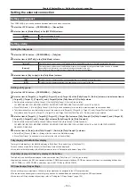
When a plug-in software application is introduced, some functions inherent to that application may be added as functions to be assigned.
r
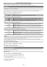
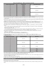
Tally output function list
f
This table describes cases when [Tally Group1], [Tally Group2], [Tally Group3], or [Tally Group4] is selected in [Group Select].
[Tally Select]
Signal name
Description
[Type]
[Input1-20]
SDI IN1 to SDI IN20
SDI input signals 1 to 20
[LowLevel] or [HighLevel]
[Input21-40]
SDI IN21 to SDI IN32
SDI input signals 21 to 32
DVI IN1 to DVI IN2
DVI-D input signal
[Internal]
Still 1V to Still 4V
Video memory (photo) 1 to 4 videos
Still 1K to Still 4K
Video memory (photo) 1 to 4 keys
Clip 1V to Clip 4V
Video memory (video) 1 to 4 videos
Clip 1K to Clip 4K
Video memory (video) 1 to 4 keys
CBGD1, CBGD2
Color background 1, 2
[MEOut]
ME1PGM, ME2PGM
Program video signal
ME1PVW, ME2 PVW
Preview video signal
ME1CLN, ME2CLN
Clean signal
DSKPGM1, DSKPGM2
Program video signal
DSKPVW1, DSKPVW2
DSK preview video signal
DSK1CLN to DSK4CLN
Clean signal
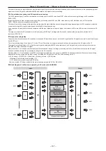
[AUX]
AUX1 to AUX16
AUX video signal
Summary of Contents for AV-HS60C1E
Page 5: ...Please read this chapter and check the accessories before use Chapter 1 Overview ...
Page 52: ...This chapter describes menu operations Chapter 5 Basic Operations ...
Page 162: ...This chapter describes the difference with the Standard mode Chapter 9 3G mode 4K mode ...
Page 168: ...This chapter describes the terminals and signals of the unit Chapter 10 External Interfaces ...
Page 184: ...This chapter describes the setting menu table and terms Chapter 12 Appendix ...
Page 206: ...Web Site http www panasonic com Panasonic Corporation 2014 ...

