– 135 –
Chapter 7 CONFIG Menu — Setting the operation mode
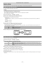
Setting the operation mode
Setting the operation mode for the crosspoint buttons
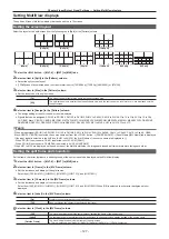
Selecting a bus using the SHIFT function
The SHIFT function is used to assign four sources to one crosspoint button (the KEY, PGM/A, or PST/B crosspoint button) and change pages using the
<2nd PAGE>/<3rd PAGE> buttons on the right of the source name display panel.
There are two operation methods for the SHIFT function:
All SHIFT
Use the <2nd PAGE>/<3rd PAGE> buttons to change all source pages for the crosspoint buttons included in the
corresponding ME at once.
Single SHIFT
Operate by assigning the <2nd PAGE>/<3rd PAGE> button to the crosspoint buttons with the menu.
Use the assigned button to change the source page of the crosspoint buttons included in the corresponding ME on a bus
basis. In this case, the <2nd PAGE>/<3rd PAGE> buttons on the right of the source name display panel can be used to
switch the source name displays.
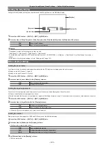
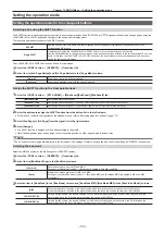
The <2nd PAGE>/<3rd PAGE> buttons can be used in two modes.
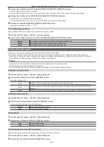
1
Select the <CONF> button
→
[OPERATE]
→
[Transition] tab.
2
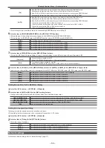
Set an item in [2nd Page Button] and [3rd Page Button] in the [Page Mode] column.
[Normal]
Enabled only while the button is pressed.
[Page Lock]
Enabled and disabled every time the button is pressed.
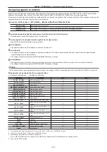
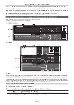
Assign the SHIFT function to the crosspoint buttons
1
Select the <CONF> button
→
[XPT ASSIGN]
→
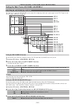
[MainPanel]/[SubPanel1]/[SubPanel2] tab.
[MainPanel] tab
Assigns the main control panel.
[SubPanel1] tab
Assigns the sub control panel 1 (second Control Panel AV-HS60C1/AV-HS60C2/AV-HS60C4).
[SubPanel2] tab
Assigns the sub control panel 2 (third Control Panel AV-HS60C1/AV-HS60C2/AV-HS60C4).
2
Select the buttons to assign the SHIFT function from the button list in the left column.
f
3
Select [2nd Page] or [3rd Page] from the signal list in the right column.
4
Select [Assign].
f
The SHIFT function is assigned to the button selected in the step
f
Once the assignment is set on one page, the corresponding button on other pages works in a same way.
@
@
NOTE
t
The 24 buttons for each page are displayed in the left column. The settings for first 16 are applied when the Control Panel AV‑HS60C4 is connected.
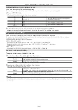
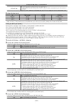
Selecting the bus mode
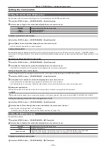
Select the A/B bus system or the flip‑flop system (PGM/PST system).
1
Select the <CONF> button
→
[OPERATE]
→
[Transition] tab.
2
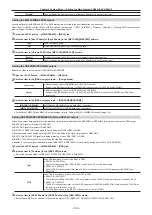
Set an item in [Bus Mode Type] in the [Bus Mode] column.
[Common]
Sets the same bus mode in ME1 and ME2.
Setting of the [Bus Mode] column
→
[Bus Mode] is applied to both ME1 and ME2.
[Each]
Different bus modes can be set for ME1 and ME2.
Settings of the [Each Bus Mode1] column
→
[Bus Mode ME1] and [Bus Mode ME2] are applied to ME1 and ME2
respectively.
3
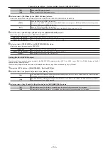
Select an item in [Bus Mode] in the [Bus Mode] column, and [Bus Mode ME1]/[Bus Mode ME2] in the [Each Bus Mode1] column.
[A/B]
When the fader lever is at side A, the signals selected on the A bus are used as the source of the PGM bus.
When the fader lever is at side B, the signals selected on the B bus are used as the source of the PGM bus.
[PGM‑A/PST‑B]
Using a flip‑flop system, the signals selected on the A bus are always used as the source of the PGM bus, and the
signals selected on the B bus are always used as the source of the PST bus.
[PGM‑B/PST‑A]
Using a flip‑flop system, the signals selected on the B bus are always used as the source of the PGM bus, and the
signals selected on the A bus are always used as the source of the PST bus.
Summary of Contents for AV-HS60C1E
Page 5: ...Please read this chapter and check the accessories before use Chapter 1 Overview ...
Page 52: ...This chapter describes menu operations Chapter 5 Basic Operations ...
Page 162: ...This chapter describes the difference with the Standard mode Chapter 9 3G mode 4K mode ...
Page 168: ...This chapter describes the terminals and signals of the unit Chapter 10 External Interfaces ...
Page 184: ...This chapter describes the setting menu table and terms Chapter 12 Appendix ...
Page 206: ...Web Site http www panasonic com Panasonic Corporation 2014 ...

