– 101 –
Chapter 5 Basic Operations — Memory
t
A registered register memory can be overwritten.
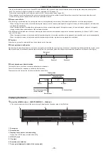
Recalling the macro register memory (playback)
Recall macros in the work memory from the registered register memory.
1
Select the <MEM> button
→
[MACRO]
→
[Register] tab.
2
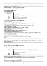
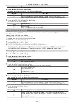
Select [Recall] in the [Register] column.
f
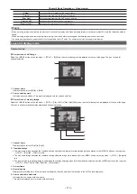
The [Recall] screen is displayed.
f
When [Recall] is selected, playback target items cannot be selected.
f
All registered operations are recalled to the work memory regardless of the registered target item selected during macro register memory
registration.
[View]
Select the display mode.
[ALL]: Displays all the memory including the unregistered register memory.
[Exist]: Displays only the registered register memory.
[Page]
Switches pages.
[Cancel]
Closes the [Recall] screen without recalling the target.
[OK]
Closes the [Recall] screen after recalling the target.
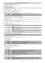
Editing macro register memories
Delete a registered register memory or change file names.
1
Select the <MEM> button
→
[MACRO]
→
[Register] tab.
2
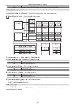
Select [Misc] in the [Register] column.
f
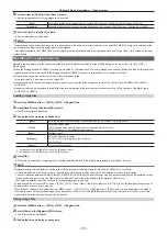
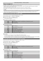
The [Misc] screen is displayed.
[Rename]
Select [Rename] after selecting a file icon to change the file name using the on‑screen keyboard.
[Delete]
Select [Delete] after selecting a file icon to delete the register memory.
[View]
Select the display mode.
[ALL]: Displays all the memory including the unregistered register memory.
[Exist]: Displays only the registered register memory.
[Page]
Switches pages.
[Close]
Closes the [Misc] screen.
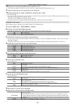
Playing back a macro bus on the Control Panel AV‑HS60C1/AV‑HS60C2/AV‑HS60C4
The playback trigger of a macro can be assigned to the KEY bus crosspoint buttons.
Assign the register memory of the macro to the crosspoint buttons of the macro bus (AV-HS60C1/AV-HS60C2: 1 to 24, AV-HS60C4: 1 to 16).
The assignment is shared between the macro busses of the ME1 and the ME2 within single Control Panel AV-HS60C1/AV-HS60C2/AV-HS60C4.
1
Select the <MEM> button
→
[MACRO]
→
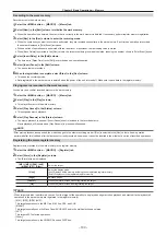
[XPT Assign] tab.
f
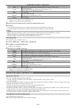
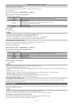
The macro register memories in the right column are assigned to the crosspoints in the left column.
[Panel‑ID]
Select the target Control Panel AV-HS60C1/AV-HS60C2/AV-HS60C4 from the [MainPanel], [SubPanel1], or [SubPanel2].
[Button Group]
Switches the page of the macro bus.
[Assign]
Assigns the macro register memories selected in the right column to the crosspoint buttons selected in the left column.
[Page Select]
Switches pages.
@
@
NOTE
t
Select the <MCRO> button using the KEY bus selector buttons in the crosspoint area on the Control Panel AV-HS60C1/AV-HS60C2/AV-HS60C4 to
play back the register memory of the macro memory assigned to the KEY bus crosspoint buttons.
At this time, the assigned macro name is displayed at the top of the source name display panel. If the <MCRO> is pressed and held, the assigned
macro name is displayed in the middle of the source name display panel.
t
The following settings can be selected in addition to the macro register memory in the right column.
- [Play Cancel]: Canceling the macro playback
- [Play Resume]: Resuming of paused macro playback
- [No Assign]: Canceling the setting assigned to the crosspoint button
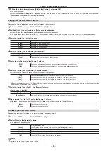
Playing back using macro attach on the Control Panel AV‑HS60C1/AV‑HS60C2/AV‑HS60C4
A trigger to play back each register memory of the macro memory can be assigned to the following buttons.
Crosspoint buttons of ME1/ME2 (PGM/A bus, PST/B bus, KEY1 to KEY4 buses, AUX1 to AUX8 buses), and the <AUTO>, <CUT>, <KEY1 TRNS> to
<KEY4 TRNS> buttons of ME1/ME2
1
Select the <MEM> button
→
[MACRO]
→
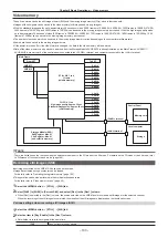
[Macro Attach] tab.
f
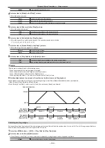
The playback trigger buttons in the right column are assigned to the macro register memories in the left column.
[Insert]
Inserts the copy of the macro same as that of the line selected in the left column in the next line. The number of buttons
to which a macro can be attached is a maximum four per register memory.
Summary of Contents for AV-HS60C1E
Page 5: ...Please read this chapter and check the accessories before use Chapter 1 Overview ...
Page 52: ...This chapter describes menu operations Chapter 5 Basic Operations ...
Page 162: ...This chapter describes the difference with the Standard mode Chapter 9 3G mode 4K mode ...
Page 168: ...This chapter describes the terminals and signals of the unit Chapter 10 External Interfaces ...
Page 184: ...This chapter describes the setting menu table and terms Chapter 12 Appendix ...
Page 206: ...Web Site http www panasonic com Panasonic Corporation 2014 ...

