– 120 –
Chapter 6 Input/Output Signal Settings — Setting input signals
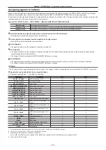
@
@
NOTE
t
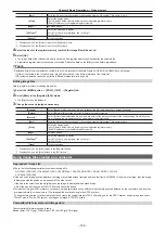
When the frame synchronizer function is [Off], if [Dot by Dot], [U/C], and [Auto] are set, the frame synchronizer function is automatically set to [Strict].
t
When [Freeze] is set to [On] in the [SDI IN 1] to [SDI IN 32] columns, the input mode cannot be changed.
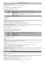
Setting the delay amount
The input signals can be delayed.
f
This function is enabled when [FS] in the [SDI IN 27]/[SDI IN 28]/[SDI IN 31]/[SDI IN 32] column is set to an item other than [Off].
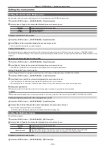
1
Select the <IN OUT> button
→
[SDI IN]
→
[Frame Buffer] tab.
2
Set [Frame delay] in the [SDI IN 1] to [SDI IN 32] columns.
f
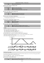
Set the input signal delay amount in a range between [0F] and [8F].
Freezing input signals
The input signals can be frozen and used. While signals are frozen, the tally signals of the corresponding input will not be output.
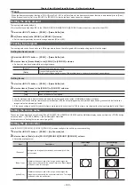
Setting the freeze mode
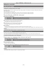
1
Select the <IN OUT> button
→
[SDI IN]
→
[Frame Buffer] tab.
2
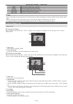
Select an item in [Freeze Mode] in the [SDI IN 1] to [SDI IN 32] columns.
f
An item can also be selected while an image is frozen.
[Frame]
Freezes the images frame by frame.
[Field]
Freezes the images field by field.
This is used to freeze moving images. With interlace signals, however, diagonal lines appear jagged.
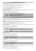
Setting freeze
1
Select the <IN OUT> button
→
[SDI IN]
→
[Frame Buffer] tab.
2
Select an item in [Freeze] in the [SDI IN 1] to [SDI IN 32] columns.
[On]
Freezes the input signals.
[Off]
Does not freeze the input signals.
f
The [F] mark appears in front of the source name when the signals set for output of MultiView displays are frozen.
f
When the unit is used with the frame synchronizer function [Off], the output images may be disturbed when freezing is executed, but the frozen
images will not be adversely affected.
f
If the freeze setting is set to [On] while the frame synchronizer function is set to [Off], the frame synchronizer function is automatically set to [Strict].
Setting the source name
The source names displayed on the Control Panel AV-HS60C1/AV-HS60C2/AV-HS60C4 and the MultiView display can be set from the <CONF> button
on the top menu
→
[SOURCE NAME]
→
[Panel Name]/[MV Name] tab.
For details, refer to “Setting the source name” (page 132).
Setting the up‑converter
In the [SDI IN 27], [SDI IN 28], [SDI IN 31], [SDI IN 32] columns, configure the built‑in up‑converter setting.
1
Select the <IN OUT> button
→
[SDI IN]
→
[Up Converter] tab.
2
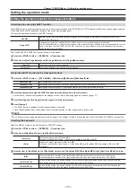
Select an item in [Scale] in the [SDI IN 27]/[SDI IN 28]/[SDI IN 31]/[SDI IN 32] column.
f
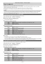
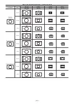
Select the scaling system.
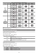
Item
Description
Input image
(SD)
System image
(HD)
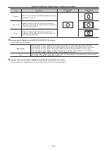
[Squeeze]
Enlarges the image both horizontally and vertically to fill the
entire screen.
[Edge Crop]
Maintains the aspect ratio of the image, and enlarges the
image in accordance with the vertical resolution. Black images
are added at the left and right.
[Letter Box]
Maintains the aspect ratio of the image, and enlarges the
image in accordance with the horizontal resolution. The image
is cropped at the top and bottom.
Summary of Contents for AV-HS60C1E
Page 5: ...Please read this chapter and check the accessories before use Chapter 1 Overview ...
Page 52: ...This chapter describes menu operations Chapter 5 Basic Operations ...
Page 162: ...This chapter describes the difference with the Standard mode Chapter 9 3G mode 4K mode ...
Page 168: ...This chapter describes the terminals and signals of the unit Chapter 10 External Interfaces ...
Page 184: ...This chapter describes the setting menu table and terms Chapter 12 Appendix ...
Page 206: ...Web Site http www panasonic com Panasonic Corporation 2014 ...

