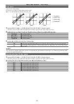
– 72 –
Chapter 5 Basic Operations — KEY
2
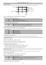
Set [PinP] in the [Mode] column.
[OFF]
Disables PinP.
[ON]
Enables PinP.
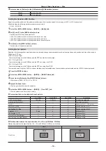
The transition effect is fixed to MIX regardless of the key transition mode settings.
Setting the PinP shape
1
Select the <ME1>/<ME2> button
→
[KEY1] to [KEY4]
→
[PinP Adjust] tab.
2
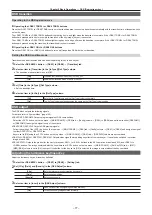
Set [Full Key] in the [Mode] column.
[OFF]
Adds the DVE effect to the key signal generated based on key type settings and cuts out the key fill signal. (Flying key
effect)
[ON]
Adds the DVE effect to the full key signal and cuts out the key fill signal regardless of the key type settings.
3
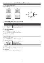
Select an item in [WipeMask] in the [Mode] column.
f
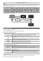
Select [Off] (square), [Circle] (circle), [Heart] (heart), [Flower] (flower), or [Star] (star), for the PinP shape.
f
This setting is enabled only when [Full Key] is set to [ON].
@
@
NOTE
t
When [Chroma] is selected as the key type, the processed foreground image is output if [PinP] is set to [ON] and [Full Key] is set to [ON] in the
[Mode] column. For details on the processed foreground image, refer to “Fine-tuning the noise or transparency of the image” (page 68).
Adjusting PinP
Adjusting the position and size
1
Select the <ME1>/<ME2> button
→
[KEY1] to [KEY4]
→
[PinP Adjust] tab.
2
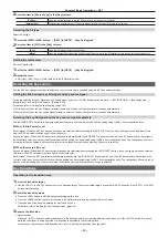
Set [X] and [Y] in the [Position] column.
f
Set the PinP position.
3
Set [Size] in the [Position] column.
f
Set the PinP size.
f
Up to 400% can be set for [KEY1] and [KEY2]. 100% or above setting is disabled when an item other than [Off] is selected in [WipeMask] in the
[Mode] column.
f
Up to 100% can be set for [KEY3] and [KEY4].
4
Set [X], [Y], and [Z] in the [Rotation] column.
f
Set the tilt for the PinP image.
f
This setting is available only for [KEY1] and [KEY2].
f
[X] and [Y] will be disabled when anything other than [Off] is selected in [WipeMask] in the [Mode] column.
5
Set [X‑Aspect] and [Y‑Aspect] in the [Rotation] column.
f
Set the aspect ratio for the PinP image.
f
This can be set only for [KEY1] and [KEY2].
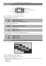
Setting [Dot by Dot]
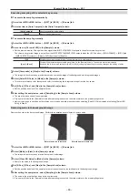
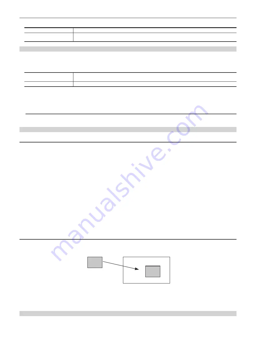
Create an actual size composition if an SD format image is used as the PinP source when the system is set to HD format. In this mode, the SD format
image will not be up-converted so image deterioration can be prevented.
f
[Size] in the [Position] column is disabled.
SD
HD
SD
Key signal
PinP composition
1
Select the <IN OUT> button
→
[SDI IN]
→
[Frame Buffer] tab.
2
Select [Dot by Dot] in [Mode] in the [SDI IN 1] to [SDI IN 32] columns.
Setting the PinP link
When [PinP] effects are added by another keyed in the same ME, it is possible to set an image to the values symmetrical to the axis whose coordinates
and rotation angle have been set. The image serving as the reference is the PinP image of the keyed being operated.
1
Select the <ME1>/<ME2> button
→
[KEY1] to [KEY4]
→
[PinP Adjust] tab.
2
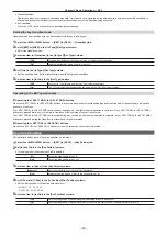
Select an item in [Sync] in the [Mode] column.
Summary of Contents for AV-HS60C1E
Page 5: ...Please read this chapter and check the accessories before use Chapter 1 Overview ...
Page 52: ...This chapter describes menu operations Chapter 5 Basic Operations ...
Page 162: ...This chapter describes the difference with the Standard mode Chapter 9 3G mode 4K mode ...
Page 168: ...This chapter describes the terminals and signals of the unit Chapter 10 External Interfaces ...
Page 184: ...This chapter describes the setting menu table and terms Chapter 12 Appendix ...
Page 206: ...Web Site http www panasonic com Panasonic Corporation 2014 ...


