162
Status Areas
Section 6-2
Output Data
6-2
Status Areas
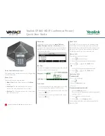
A Temperature Input Unit has two internal Status Areas. Bits are set with
respect to thresholds set by the user for each function. When any bit turns ON
in one of these Status Areas, the relevant Communications Unit Status Flag
turns ON. The Master Unit is notified of the status of Communications Unit
Status Flags. Information in I/O Unit Status Areas can be read using the Set-
ting Tool.
GRT1-TS2
@
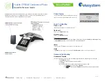
Warning Status Area
A Temperature Input Unit’s Warning Status Area is configured of the following
16 bits. The Warning Status Area provides notification of minor errors in the
Unit.
Temperature Status Flags
(2 input bytes)
Used to allocate the bits for the Comparator Result Flags, Top/Valley Detection Timing
Flags, and Off-wire Detection Flags. The function of each bit is as follows:
• Comparator Result Flags
Allow control of the judgement results only, without allocating temperature values
• Top/Valley Detection Timing Flags
Used to time reading the values held as the top and valley values when both the top and
value values are allocated at the same time.
• Off-wire Detection Flags
Disconnections can be detected even when the temperature values are not allocated.
Temperature Data Normal
D Top/Valley Detec-
tion Timing Flags (6 input
bytes)
Allocation of the Temperature Data followed by the Top/Valley Detection Timing Flags.
Temperature Data 1/100 Dis-
play + Top/Valley Detection
Timing Flags (10 input bytes)
Input data
Details
Output data
Details
Hold Flags (1 output byte)
Used with each of the hold functions (peak, bottom, top, and valley) to control the execu-
tion timing of hold functions from the Master.
Master
Comm
u
nications Unit
Temperat
u
re Inp
u
t Unit
If the Temperat
u
re Inp
u
t Unit Stat
u
s Flag
t
u
rns ON, the relevant Comm
u
nications
Unit Stat
u
s Flag
w
ill t
u
rn ON.
The threshold is exceeded
and the relevant
b
it t
u
rns ON.
The Setting Tool can
b
e
u
sed
to read
w
hich
b
its are ON.
Notification to
Master
Bit
Contents
Description
0
Reserved.
---
1
Reserved.
---
2
Reserved.
---
3
Unit Maintenance Flag
OFF: Normal; ON: Error
(Over threshold or 87672
hours)
Monitors the power-ON time set as the
threshold for the Unit conduction time
monitoring function.
Also monitors whether 87672 hours (10
years) have elapsed.
Summary of Contents for SMARTSLICE GRT1-DRT
Page 1: ...OPERATION MANUAL Cat No W455 E1 08 SmartSlice GRT1 Series Slice I O Units ...
Page 3: ...SmartSlice GRT1 Series Slice I O Units Operation Manual Revised December 2018 ...
Page 4: ...iv ...
Page 6: ...vi ...
Page 20: ...xx EC Directives 6 ...
Page 62: ...42 Connecting Turnback Cables Section 3 3 ...
Page 250: ...230 Maintenance Information Window Section 7 3 Maintenance Information Window ...
Page 292: ...272 GRT1 CP1 L Positioning Unit Section 7 5 ...
Page 300: ...280 GRT1 END End Unit Section 8 5 Dimensions 11 9 11 9 55 7 1 5 19 5 83 5 2 9 2 9 OMRON ...
Page 322: ...302 Troubleshooting by Unit Section 9 5 ...
Page 350: ...330 Explicit Messages Appendix A ...
Page 354: ...334 Power Consumption and Weight Tables Appendix C ...
Page 356: ...336 I O Current Consumption Table Appendix D ...
Page 364: ...344 Revision History ...
Page 365: ......