121
Analog Input Units
Section 5-4
■
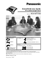
Example of Valley Hold
Note
1. A delay in network transmission time will occur from the time the Hold Flag
turns ON (or OFF) in the Master’s ladder program until notification of the
flag’s status is actually sent to the Unit. Therefore, even when the Hold
Flag is ON, the first analog data transmitted to the Master when the CPU
Unit power is turned ON may be the data from when the Hold Flag was
OFF. To collect top/valley hold data using the Hold Flag at the Master, con-
figure a ladder program which considers the transmission delay time when
the Hold Flag is turned ON, then enables the top/valley hold values after a
fixed time interval.
2. The time that the Top/Valley Detection Timing Flags are ON can be adjust-
ed by setting the one-shot time. Use the Setting Tool to set the one-shot
time (the setting range is 1 to 65535 ms).
3. If the Hold Flag turns OFF during the time the Top/Valley Detection Timing
Flag is set to be ON, both flags will turn OFF simultaneously.
Setting Procedure (Example: DeviceNet Configurator)
1,2,3...
1. In the Network Configuration Window for the Slice I/O Terminal, double-
click the icon of the Slice I/O Terminal that is to be set. Alternatively, right-
click the icon and select
Parameters - Edit
. The Edit Device Parameters
Window will be displayed.
2. Click the
I/O Module
Tab.
3. Click the
Edit
Button on the
I/O Module
Tab Page. The Edit Unit Parame-
ters Window will be displayed.
Analog input value
Valley hold value
Last value is held.
Hold value
Hold Flag
Hold function starts
Hold function stops
Top/Valley Detection
Timing Flag
One-shot time
Summary of Contents for SMARTSLICE GRT1-DRT
Page 1: ...OPERATION MANUAL Cat No W455 E1 08 SmartSlice GRT1 Series Slice I O Units ...
Page 3: ...SmartSlice GRT1 Series Slice I O Units Operation Manual Revised December 2018 ...
Page 4: ...iv ...
Page 6: ...vi ...
Page 20: ...xx EC Directives 6 ...
Page 62: ...42 Connecting Turnback Cables Section 3 3 ...
Page 250: ...230 Maintenance Information Window Section 7 3 Maintenance Information Window ...
Page 292: ...272 GRT1 CP1 L Positioning Unit Section 7 5 ...
Page 300: ...280 GRT1 END End Unit Section 8 5 Dimensions 11 9 11 9 55 7 1 5 19 5 83 5 2 9 2 9 OMRON ...
Page 322: ...302 Troubleshooting by Unit Section 9 5 ...
Page 350: ...330 Explicit Messages Appendix A ...
Page 354: ...334 Power Consumption and Weight Tables Appendix C ...
Page 356: ...336 I O Current Consumption Table Appendix D ...
Page 364: ...344 Revision History ...
Page 365: ......