


101
Analog Input Units
Section 5-4
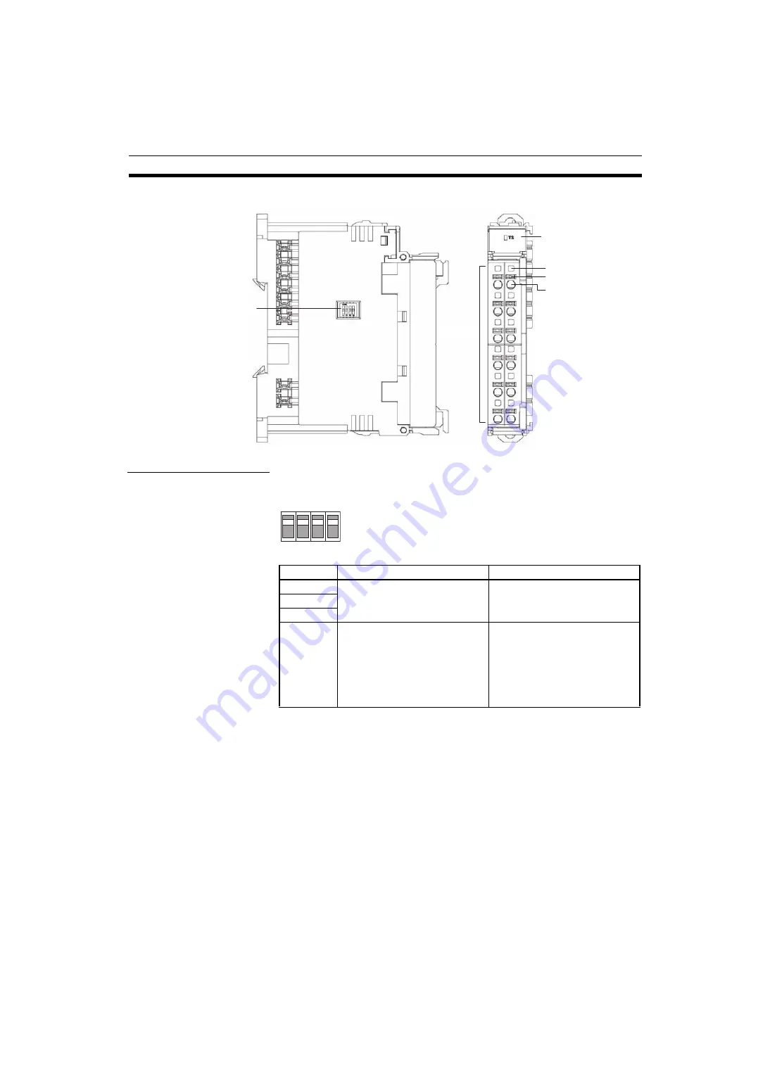
Names and Functions of Parts
Setting the Input Range
Setting with the DIP
Switch
The input signal range can be set using the DIP switch or the Setting Tool.
Each pin is set according to the following table.
Note
1. Always set pin 4 to ON if the DIP switch is to be used to set the ranges. If
this pin is OFF, the DIP switch settings will not be enabled.
2. The DIP switch settings are read when the power is turned ON.
3. If pin 4 is set to ON, you will not be able to set any functions, including the
range setting, from the Setting Tool. Always set pin 4 to OFF when using
the Setting Tool.
DIP S
w
itch
Used to set
inp
u
t range.
Terminal
Block
LED Indicator
Displays Unit stat
u
s.
Test Pins
Terminal Insertion Holes
Release B
u
ttons
Pin No.
Setting
Specifications
1
Input Terminal: Input range setting
for Inputs 0 and 1.
Default setting: All pins OFF
2
3
4
Input range setting method
OFF: Set using Setting Tool.
ON: Set using DIP switch. (The
DIP switch settings are dis-
abled when this pin is OFF,
i.e., when the Setting Tool is
used.)
Note
Default setting: OFF
1
2
3
4
Summary of Contents for SMARTSLICE GRT1-DRT
Page 1: ...OPERATION MANUAL Cat No W455 E1 08 SmartSlice GRT1 Series Slice I O Units ...
Page 3: ...SmartSlice GRT1 Series Slice I O Units Operation Manual Revised December 2018 ...
Page 4: ...iv ...
Page 6: ...vi ...
Page 20: ...xx EC Directives 6 ...
Page 62: ...42 Connecting Turnback Cables Section 3 3 ...
Page 250: ...230 Maintenance Information Window Section 7 3 Maintenance Information Window ...
Page 292: ...272 GRT1 CP1 L Positioning Unit Section 7 5 ...
Page 300: ...280 GRT1 END End Unit Section 8 5 Dimensions 11 9 11 9 55 7 1 5 19 5 83 5 2 9 2 9 OMRON ...
Page 322: ...302 Troubleshooting by Unit Section 9 5 ...
Page 350: ...330 Explicit Messages Appendix A ...
Page 354: ...334 Power Consumption and Weight Tables Appendix C ...
Page 356: ...336 I O Current Consumption Table Appendix D ...
Page 364: ...344 Revision History ...
Page 365: ......


