background image

4 - 23

LLE11ARDA001A/E

Replace the CA23 cable (40350-CA23) with the new
one.

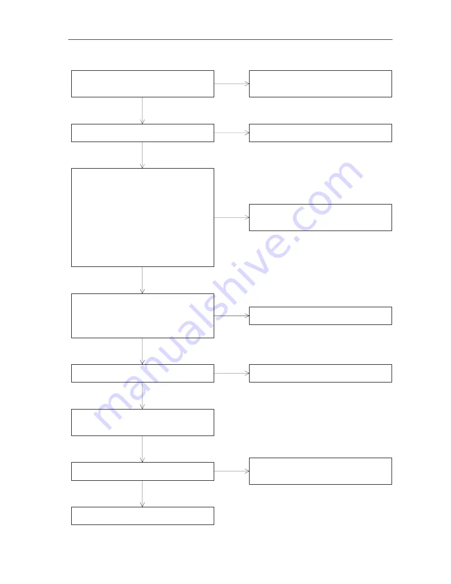
Deos the CA23 cable (40350-CA23) break?

Is there a continuity between the following connectors
on the BA06 board (40350-BA06)?
P601(J1) connector - P606(J6) connector

7

-

1 pins

8

-

2 pins

9

-

3 pins

10

-

4 pins

11

-

5 pins

12

-

6 pins

P601(J1) connector - P608(J8) connector

13(14)

-

1 pins

18

-

2 pins

Is the voltage between the 2-GND of the P608(J8) as
described below when shading the sensor of the CA41
cable (40350-CA41)?
The sensor is shaded.

:DC 0V

The sensor is not shaded.

:DC+5V

Does the CA12 cable (40350-CA12) with the new one.

Replace the BA06 board (40350-BA06) with the new
one.
(See 6.1.6.)

Replace the CA41 cable (40350-CA41) with the new
one.

Replace the CA12 cable (40350-CA12) with the new
one.

No

Yes

Yes

Yes

No

No

No

Yes

Replace the BA02 board (40350-BA02) with the new
one.
(See 6.1.2.)

Replace the BA01 board (40350-BA01) with the new
one.
(See 6.1.1.)

Is the symptom improved?

No

Yes

Is the voltage between the 13-15 (14-16) pins of the
P211(J11) connector on the BA02 board (40350-
BA02) DC+5V?

Replace the BA02 board (40350-BA02) with the new
one.
(See 6.1.2.)

Yes

No

Completion

4.3.3.12 412-Drill R Initialize error is displayed.

Summary of Contents for ME-1000

Page 1: ...NIDEK MULTIFUNCTION EDGER Model ME 1000 SERVICE MANUAL September 2005 LLE11ARDA001A E 134 pages in Total...

Page 2: ...o Office Chiyoda ku Tokyo 101 0051 Japan Telephone 03 3288 0571 Facsimile 03 3288 0570 Telex 2226647 NIDEK J NIDEK INCORPORATED 47651 Westinghouse Drive Fremont California 94539 U S A United States Ag...

Page 3: ...is displayed 4 18 4 3 3 5 405 XY Initialize error is displayed 4 19 4 3 3 6 406 XR Initialize error is displayed 4 19 4 3 3 7 407 YR Initialize error is displayed 4 19 4 3 3 8 408 Front feeler Initia...

Page 4: ...URE 6 1 6 1 Replacing the Printed Board 6 1 6 1 1 Replacing the BA01 printed board 6 1 6 1 2 Replacing the printed board BA02 6 1 6 1 3 Replacing the printed board BA03 6 2 6 1 4 Replacing the printed...

Page 5: ...placing the Pulse Motor Driver 6 25 6 23 1 Replacing theAlfa step motor driver for the X axis 6 25 6 23 2 Replacing theAlfa step motor driver for theYaxis 6 25 6 23 3 Replacing theAlfa step motor driv...

Page 6: ...10 GrooveAdjustment 7 20 7 10 1Adjustingthegroovingdepth 7 20 7 10 2Adjustingthegrooveposition 7 21 7 10 3Adjusting the GrooveAXIS 7 22 7 11DrillingAdjustment 7 23 7 11 1Preparationforthedrillingadju...

Page 7: ...t is necessary to understand this manual thoroughly before servicing Refer to the NIDEK multifunction edger model ME 1000 Operator s Manual and Parts List Specifications are subject to change without...

Page 8: ...1 2 LLE11ARDA001A E...

Page 9: ...drop parts or screws inside the instrument nor bump it against the surrounding objects Have storage cases ready to ensure the loss of the removed screws or parts In screwing or unscrewing use a proper...

Page 10: ...ding wheels may become damaged Never fail to shut the soundproof cover while the wheels are turning Otherwise grinding splash may get in your eye and hurt it While rotating wheels and V belt never bri...

Page 11: ...not Appear 4 7 The Feeler does not Contact to the Lens 4 8 The Lens Processing cannot be Performed Properly Yes Yes Yes No Yes No No No No 4 3 The Error Message Appears Yes Can the system be operated...

Page 12: ...3 2 LLE11ARDA001A E...

Page 13: ...5 pins of the connector P201 J2 on the BA02 board 40350 BA02 DC 24V Is the voltage of the connector on the BA02 board 40350 BA02 as described below Connector P202 J2 Between 1 2 pins DC 12V Between 3...

Page 14: ...303 connector DC 12V Does the LCD cable 40273 E022 break Does the CA30 cable 40350 CA30 break Replace the color LCD module 42203 E016 with the new one See 6 8 Replace the BA01 board 40350 BA01 with th...

Page 15: ...Replace the CA12 cable 40350 CA12 with the new one Does the CA12 cable 40350 CA12 break Replace the BA01 board 40350 BA01 with the new one See 6 1 1 Is the symptom improved Replace the BA02 board 4035...

Page 16: ...d Yes No 4 3 2 3 Error code 203 Feeler lift error is displayed Is the error code 203 Feeler lift error displayed Yes No 4 3 2 4 Error code 204 Front rear data crossed is displayed Is the error code 20...

Page 17: ...ze error is displayed Is the error code 408 Front feeler Initialize error displayed Yes No 4 3 3 9 Error code 409 Rear feeler Initialize error is displayed Is the error code 409 Rear feeler Initialize...

Page 18: ...played Is the error code 603 SFB wheel was not rotate displayed Yes No 4 3 6 1 Error code 701 Cover open error is displayed Is the error code 701 Cover open error displayed Yes No 4 3 6 2 Error code 7...

Page 19: ...alfa step pulse motor 40347 E030 break Replace the Y axis AS 40350 5300 with the new one See 6 17 Replace the Y axis AS 40350 5300 with the new one See 6 17 Yes No Yes No No Yes Replace the BA02 board...

Page 20: ...s the wheel See 7 2 3 Is the maximum processing rotation number 40 Select 40 of the maximum processing rotation number No Yes Check the operation of the Y axis by hand when the X axis of the carriage...

Page 21: ...ight lens measuring AS 40350 4200 break Replace the DC motor 40350 E047 of the right lens measuring AS 40350 4200 with the new one See 6 20 2 No Yes Does the right feeler AS 40350 4220 move smoothly w...

Page 22: ...reak Replace the rotary encoder 40350 E035 of the right lens measuring AS 40350 4200 with the new one See 6 21 2 No Yes Does the CA14 cable 40350 CA14 break Replace the CA14 cable 40350 CA14 with the...

Page 23: ...4 11 LLE11ARDA001A E 4 3 2 2 202 There is no lens is displayed Place the lens Is the lens placed 4 3 2 1 Error code 201 Feeler off error No Yes...

Page 24: ...board 40350 BA07 of the left lens measuring AS 40350 4100 and right lens measuring AS 40350 4200 with the new one See 6 1 7 Replace the CA32 cable 40350 CA32 of the left lens measuring AS 40350 4100 w...

Page 25: ...new one See 6 1 1 Completion No Yes Is the symptom improved Completion No Yes Is the voltage between 6 4 pins of the P705 J5 connector on the BA07 board 40350 BA07 of the right lens measuring AS 40350...

Page 26: ...one No Yes Does the rotary encoder 40350 E035 of the right lens measuring AS 40350 4200 break Replace the rotary encoder 40350 E035 of the right lens measuring AS 40350 4200 with the new one See 6 21...

Page 27: ...one See 6 1 1 Completion Yes No No Perform the calibration of the lens measuring unit See 7 3 Perform the adjustment of the feeler See 7 4 Is the symptom improved Completion Yes No 4 3 2 5 205 Start e...

Page 28: ...e Replace the alfa step motor 40347 E030 of the X axis AS 40350 5120 with the new one See 6 22 1 Replace the CA35 cable 40350 CA35 with the new one Yes Yes No No Yes No Is the symptom improved Replace...

Page 29: ...0 of the Y axis AS 40350 5300 with the new one See 6 22 2 Replace the CA36 cable 40350 CA36 with the new one Yes Yes No No Yes No Is the symptom improved Replace the BA02 board 40350 BA02 with the new...

Page 30: ...0 of the Y axis carriage AS 40350 5200 with the new one See 6 22 3 Replace the CA36 cable 40350 CA37 with the new one Yes Yes No No Yes No Is the symptom improved Replace the BA02 board 40350 BA02 wit...

Page 31: ...yed Perform the procedures described in 4 3 3 2 and 4 3 3 3 4 3 3 6 406 XR Initialize error is displayed Perform the procedures described in 4 3 3 2 and 4 3 3 4 4 3 3 7 407 YR Initialize error is disp...

Page 32: ...ector 7 1 pins 8 2 pins P701 J1 connector P704 J4 connector 1 1 pins 5 2 pins P701 J1 connector P705 J5 connector 1 1 pins 6 2 pins Replace the BA02 board 40350 BA02 with the new one See 6 1 2 Is the...

Page 33: ...r 1 1 pins 4 4 pins P701 J1 connector P703 J3 connector 7 1 pins 8 2 pins P701 J1 connector P704 J4 connector 1 1 pins 5 2 pins P701 J1 connector P705 J5 connector 1 1 pins 6 2 pins Replace the BA02 b...

Page 34: ...P607 J7 connector on the BA06 board 40350 BA06 as described below when shading the sensor of the CA40 cable 40350 CA40 The sensor is shaded DC 0V The sensor is not shaded DC 5V Does the CA12 cable 403...

Page 35: ...is shaded DC 0V The sensor is not shaded DC 5V Does the CA12 cable 40350 CA12 with the new one Replace the BA06 board 40350 BA06 with the new one See 6 1 6 Replace the CA41 cable 40350 CA41 with the...

Page 36: ...low when shading the sensor of the CA39 cable 40350 CA39 The sensor is shaded DC 0V The sensor is not shaded DC 5V Does the CA12 cable 40350 CA12 break Replace the BA05 board 40350 BA05 with the new o...

Page 37: ...S 40350 5210 with the new one See 6 22 4 Replace the CA38 cable 40350 CA38 with the new one Yes Yes No No Yes No Is the symptom improved Replace the BA02 board 40350 BA02 with the new one See 6 1 2 Ye...

Page 38: ...V with the new one See 6 25 Is the symptom improved Replace the BA02 board 40350 BA02 with the new one See 6 1 2 Replace the CA10 cable 40350 CA10 with the new one Replace the E059 cable 40347 E059 wi...

Page 39: ...ak Does the CA12 cable 40350 CA12 break Replace the BA02 board 40350 BA02 with the new one See 6 1 2 Is the symptom improved Completion Replace the DC motor with encoder 40350 E026 for grooving drilli...

Page 40: ...CA12 cable 40350 CA12 break Replace the BA02 board 40350 BA02 with the new one See 6 1 2 Is the symptom improved Completion Replace the DC motor with encoder 40350 E025 for SFB AS with the new one Re...

Page 41: ...ector for the CA33 cable 40350 CA33 as described below The cover is open There is a continuity The cover is close There is no continuity Does the CA12 cable 40350 CA12 break Replace the BA02 board 403...

Page 42: ...displayed Yes No Dress the finishing wheel for CR39 See 7 2 3 Is the message asking to dress the finishing wheel for CR39 displayed Yes No Dress the finishing wheel for glass See 7 2 3 Is the message...

Page 43: ...between the following pins of the P301 J1 connector on the BA03 board 40350 BA03 CHUCK A11 A14 pins TOUCH A13 B12 pins R L A13 B11 pins START A13 A12 pins STOP A13 A11 pins Does the CA12 cable 40350 C...

Page 44: ...nector 1 A9 pins 2 B9 pins 3 A10 pins 4 B10 pins Does the LCD cable 40273 E022 break Replace the BA01 board 40350 BA01 with the new one See 6 1 1 Is the symptom improved Completion Replace the BA03 bo...

Page 45: ...0 4200 with the new one See 6 9 No Yes 4 7 The Feeler does not Touch the Lens 4 7 1 The front feeler does not touch the lens 4 7 2 The rear feeler does not touch the lens Replace the rotary encoder 40...

Page 46: ...8 5 The bevel position is not proper Is the bevel position of the bevel proper No Yes 4 8 6 The SFB position is not proper Is the SFB position proper 4 8 7 The groove position is not proper Is the gr...

Page 47: ...nd filter with the new one Refer to the Operator s Manual Is the symptom improved Is the voltage supplied to the outlet for the pump AC100V 200 system AC200V Does the pump work Does the CA08 cable 403...

Page 48: ...justment See 7 7 Use a protective tape in processing Yes No Is the symptom improved Use the soft processing mode Yes No Completion 4 8 3 Axis shift occurs 4 8 4 Processing time is long Dress the wheel...

Page 49: ...unit with the new one See 6 9 Completion No Yes Is the symptom improved Completion Yes No Perform the bevel position adjustment See 7 6 Is the overall size of the lens proper Yes Adjust the size No En...

Page 50: ...ing unit with the new one See 6 9 Completion No Yes Is the symptom improved Completion Yes No Perform the SFB adjustment See 7 9 Is the lens measuring position proper See 7 4 Perform the feeler adjust...

Page 51: ...Is the symptom improved Replace the lens measuring unit See 6 9 Completion No Yes Is the symptom improved Completion Yes No Perform the groove adjustment See 7 10 Is the lens measuring position prope...

Page 52: ...e size Dress the polishing wheel See 7 2 3 Is the symptom improved Perform the polishing adjustment See 7 8 Completion Yes No Completion Yes No 4 8 8 Unpolished parts are left in the polishing process...

Page 53: ...5 2 Removing the front cover 1 Open the top cover AS 40350 2000 See 5 1 2 Remove SB4 12 n 4 and 3WP4 n 4 on the side 3 Remove the front cover 40350 M220 4 Reassemble the parts in reverse order 5 3 Rem...

Page 54: ...erse order 5 5 Removing the rear cover 1 Disconnect all the cables such as the power cable 2 Unscrew SB4 12 n 2 and 3WP4 n 4 3 Remove the rear cover 40350 M222 4 Reassemble the parts in reverse order...

Page 55: ...2 Replacement part 40350 BA02 1 Open the top cover AS 40350 2000 and remove the rear cover 40350 M222 See 5 1 and 5 5 2 Remove the electric operated coverAS 40350 7000 See 6 1 8 3 Disconnect all the c...

Page 56: ...4 Disconnect all the connectors on the printed board 40350 BA03 5 Unscrew PC3 6 n 4 and remove the printed board 40350 BA03 6 Reassemble the parts in reverse order 6 1 4 Replacing the printed board BA...

Page 57: ...p cover 40350 2000 See 5 1 2 Remove the electric operated coverAS 40350 7000 See 6 1 8 3 Disconnect all the connectors on the printed board 40350 BA06 4 Unscrew PC3 6 n 3 and remove the printed board...

Page 58: ...4 Reassemble the parts in reverse order 6 1 8 Replacing the printed board BA08 Replacement part 40350 BA08 1 Open the top cover AS 40350 2000 See 5 1 2 Disconnect the connector from the rear of the e...

Page 59: ...40350 BA09 4 Unscrew PC3 5 n 4 and remove the printed board 40350 BA09 5 Remove PC3 5 n 4 and spacers 82051 A310A from the printed board 40350 BA09 6 Reassemble the parts in reverse order 6 1 10 Repla...

Page 60: ...moving jig 40390 6000 to remove the grinding wheel AS 40350 1060 Turn the wheel inward to remove it since the screw channel of the wheel is reverse 3 Reassemble the parts in reverse order 6 3 Replacin...

Page 61: ...set screw 40370 M008 and remove the lens adapter 40370 8100 3 Reassemble the parts in reverse order 6 5 Replacing the Power Switch Replacement part 80460 00123 1 Open the top cover AS 40350 2000 See 5...

Page 62: ...t 80602 00101 1 Open the top cover AS 40350 2000 See 5 1 2 Remove the side cover R See 5 3 3 Disconnect all the connectors from the switching regulator 80602 00101 4 Unscrew PC4 5 n 4 and remove the s...

Page 63: ...achment sheet 40350 M206 and reassemble the parts in reverse order 6 8 Replacing the Color LCD Module Replacement part 42203 E016 1 Remove the display AS 40350 2100 See 6 1 3 2 Remove the printed boar...

Page 64: ...and remove the left lens measuring AS 40350 4100 5 Reassemble the parts in reverse order 6 9 2 Replacing the right lens measuring AS Replacement part 40350 4200 1 Open the top cover AS 40350 2000 See...

Page 65: ...ection 5 2 Slide the right and left shafts 40350 M505 M506 in the back 3 Remove the wheel See 6 2 4 Disconnect the connector of the brushless motor 40350 E010 5 Unscrew SB6 20 n 4 and remove the spind...

Page 66: ...he electric operated coverAS 40350 7000 See 6 1 8 3 Unscrew SB4 10 n 2 and remove the processing AS 40350 3300 4 Disconnect the connectors P601 J1 and P602 J2 on the printed board 40350 BA06 5 Push th...

Page 67: ...0 See the section 5 2 Disconnect the connectors P501 J1 and P502 J2 on the printed board 40350 BA05 3 Unscrew CS4 8 n 2 and remove the spindle AS 40350 6300 4 Unscrew SB3 8 n 3 and remove the arm AS 4...

Page 68: ...2 Unscrew SB4 12 n 2 and remove the cover holder L 40350 M112 Previously disconnect the cable 3 Remove the hose connecting to the ganged water supply pipe AS 40350 9300 4 Unscrew H4 4 and remove the...

Page 69: ...emove the right and left lens measuring AS 40350 4100 4200 See 6 9 4 Remove the SFB AS 40350 6000 See 6 12 5 Remove the ganged water supply AS 40350 9300 See 6 13 6 Unscrew the set screws HH4 4 n 2 of...

Page 70: ...4 4 Remove the spindle AS 40350 1400 See 6 10 5 Fully open the chucking shaft and move the carriage to the right Remove the guard R 40350 M911 and inner guard 40340 M921 6 Move the carriage to the le...

Page 71: ...order 6 17 Replacing the YAxis AS Replacement part 40350 5300 1 Remove the front cover 40350 M220 and side cover 40350 M223 See the section 5 2 Remove the pin 40350 M570 and move the pipe to the proce...

Page 72: ...40350 M435 1 Open the top cover AS 40350 2000 See 5 1 2 Unscrew HH4 4 n 2 and remove the feeler AS 40350 4120 3 Unscrew the No 0 type 1 flat head screw 40340 M994 n 2 Remove the holder 40340 M985 and...

Page 73: ...350 M436 1 Open the top cover AS 40350 2000 See 5 1 2 Unscrew HH4 4 n 2 and remove the right feeler AS 40350 4220 3 Unscrew the No 0 type 1 flat head screw 40340 M994 n 2 Remove the holder 40340 M985...

Page 74: ...tor 40350 E047 4 Reassemble the parts in reverse order The rotary encoder 40350 E035 can be removed in the same procedure 6 20 2 Replacing the DC motor of the right lens measuring AS Replacement part...

Page 75: ...rotary encoder 40350 E035 See 6 20 2 3 Reassemble the parts in reverse order 6 22 Replacing the Alfa Step Motor 6 22 1 Replacing the Alfa step motor for the X axis Replacement part 40347 E030 1 Remov...

Page 76: ...See 6 17 2 Remove the timing belt 40350 M503 3 Unscrew SB3 8 n 4 and remove the Alfa step motor 40347 E030 4 Unscrew HH4 4 n 2 and remove the pulley 40350 564 5 Reassemble the parts in reverse order...

Page 77: ...side of the Alfa step motor driver 40347 E030 and remove the pinion 40350 M516 3 Disconnect the CN2 connector of the Alfa step motor driver 40347 E031 4 Unscrew SB4 12 n 2 Remove the Alfa step motor 4...

Page 78: ...n 5 2 Unscrew SB4 10 n 2 and unclamp the cables Remove the CN2 connector from the Alfa step motor driver for CHUCK 40273 E007 3 Turn the gear and adjust its position so that the screw passes through t...

Page 79: ...X axis 40347 E031 3 Unscrew SB3 8 n 2 and remove the Alfa step motor driver 40347 E031 4 Reassemble the parts in reverse order 6 23 2 Replacing the Alfa step motor driver for the Y axis Replacement p...

Page 80: ...47 E03 3 Unscrew SB3 8 n 2 and remove the Alfa step motor driver 40347 E031 4 Reassemble the parts in reverse order 6 23 4 Replacing the Alfa step motor driver for CHUCK Replacement part 40273 E007 1...

Page 81: ...motor AS 40350 1410 3 Reassemble the parts in reverse order 6 25 Replacing the Inverter for the BL Motor Replacement part 40350 E031 1 Open the top cover AS 40350 2000 and remove the side cover L 4035...

Page 82: ...025 together with the pulley 40350 M692 6 Unscrew HH4 4 n 2 and remove the DC motor with encoder 40350 E025 7 Reassemble the parts in reverse order 6 26 2 Replacing the DC motor for the grooving drill...

Page 83: ...ble the parts in reverse order Adjust the tension of the timing belt so that its tension after the replacement is about the same as the one before the replacement 6 28 Replacing the Chuck Motor AS Rep...

Page 84: ...miter gear inside of the processing AS is worn replace the processing AS 40350 3300 with a new one as well See 6 11 Perform the mesh adjustment of the miter gear 40350 M392 6 30 Replacing the End Mil...

Page 85: ...ht to loosen it and remove the cutter 40350 M364 7 Reassemble the parts in reverse order The cutter has the orientation Attach the cutter in the direction viewing from the a direction as illustrated o...

Page 86: ...CA33 Replacement part 40350 CA33 1 Open the top coverAS 40350 2000 See 5 1 2 Disconnect the connector P803 J3 on the BA08 board 40350 BA08 3 Unscrew CK2 10 n 2 Remove the CA33 cable 40350 CA33 and th...

Page 87: ...ng the Parameter Setting mode 1 Depress MENU on the layout screen until the Parameter Setting screen appears 2 Select each item 3 Select the setting for each item 4 Press EXIT to return to the layout...

Page 88: ...item 5 Press EXIT to return to the layout screen Pressing Cancel displays the layout screen without changing the setting Pressing BACK displays the Parameter Setting screen without changing the setti...

Page 89: ...fault setting 1 CR39 Hi Index 3 2 Polyca Acrylic Trivex 3 3 Glass 2 4 After the verification press BACK to return to the Parameter Setting mode 2 2 Wheel Parameter 2 CEJKPG 6 RG 2 CEJKPG 6 RG BACK 2 2...

Page 90: ...performing the dressing Be careful to touch the dressing stick Touching the dressing stick strongly or the corner of its edge to the wheel may damage the surface of the wheel Never dress the roughing...

Page 91: ...the wheel with a brush 6 Press STOP for the wheel dressing to complete this work 7 2 4 Reading the lens data 1 Establish the Menu mode and select Maintenance See 7 1 1 2 Read the stored lens data 1 C...

Page 92: ...Establish the Parameter Setting mode See 7 1 2 3 Press Calibration 4 Perform the following calibrations 1 Wheel Calibration To perform the calibration of the wheelAXIS 2 LMU Calibration To perform the...

Page 93: ...t the feeler height when it is not 45 0 20mm 1 Establish the Parameter Setting mode See 7 1 2 2 Press Feeler Height and change the parameter setting so that the track is 45 0 20mm a Larger decrease th...

Page 94: ...EL 4 or baby powder on the lens so as to recognize the feeler s measuring track Put the lens into the processing chamber 4 Select the processing settings as below on the layout screen 1 Frame type Nyl...

Page 95: ...he value b The track slants to the left increase the value Enter 1 0 when the measuring track slants to the right in 1 toward the lens edge 8 After the parameter settings have been changed press BACK...

Page 96: ...ter for the adjustment Use the lens CR 39 diopter of 3D to 5D to adjust the size of the CR39 lens Enter 1 00 when the Finish size is 46 Measure the lens edge of the front side when measuring the flat...

Page 97: ...for the wheel type of PLB G a Bevel Position b Bevel Position Glass Entering the minus value moves the bevel position toward the front Change the parameter values in 0 05 increments Use the lens which...

Page 98: ...ca Acrylic Trivex Bevel d Polyca Acrylic Trivex Flat e Glass Bevel f Glass Flat Enter the plus value when the horizontal line slants to the right viewing from the front of the lens Change the paramete...

Page 99: ...edge is burnt When the unpolished area is left on the lens edge even after changing the parameter value of the Polishing Diff to 0 5 dress the polishing wheel since the processing performance of the p...

Page 100: ...e polishingAXIS so that the lens edge is polished evenly in the entire circumference even when the unpolished part is partly left 7 Set the parameter value of CR39 Flat as it was after the adjustment...

Page 101: ...meter is not 45 0 10mm 1 Establish the Parameter Setting mode See 7 1 2 2 Press Adjustment 3 Press Polish 4 Adjust the following parameter settings Use a lens suitable for each parameter in the adjust...

Page 102: ...ocessing are completed 1 Rear Position Flat 2 Front Position Flat 3 Rear Position Bevel 4 Front Position Bevel Inputting the plus value increases the width of the safety bevel GFKWO 5OCNN CTIG Setting...

Page 103: ...from the lens front Changing the Rear AXIS changes the Rear AXIS Polish Changing the Front AXIS changes the Front AXIS Flat 4QWIJ 5K G KPKUJ 5K G 2QNKUJ 5K G 2QNKUJ KHH 5 5CHGV GXGN TQQXG TKNN Adjust...

Page 104: ...G NCV TQPV 5K G GXGN TQPV 5K G NCV BACK 4QWIJ 5K G KPKUJ 5K G 2QNKUJ 5K G 2QNKUJ KHH 5 5CHGV GXGN TQQXG TKNN Adjustment 4GCT 2QUKVKQP NCV TQPV 2QUKVKQP NCV 4GCT 2QUKVKQP NCV 2QNKUJ TQPV 2QUKVKQP NCV 2...

Page 105: ...the right or left side of the upper lens edge viewing from the lens front 1 Change the parameter settings below when the unpolished part is left on the upper right or left side of the rear safety beve...

Page 106: ...the depth of the groove when the grooving depth is not within 0 10mm See 7 1 2 1 Establish the Parameter Setting mode See 7 1 2 2 Press Adjustment 3 Press Groove Drilling 4 Adjust the parameter settin...

Page 107: ...just the groove position when it is not in the middle of the lens edge 1 Establish the Parameter Setting mode See 7 1 2 2 Press Setting Grinding 3 Press Adjustment 4 Adjust the parameter settings belo...

Page 108: ...r settings below a CR39 Hi Index Groove b Polyca Acrylic Trivex Groove Use a lens suitable for each parameter in the adjustment Increase the adjustment value when the groove on the upper left side is...

Page 109: ...owing parameter setting a Depth X Input the minus value of the Depth X when the drill bores too much 5K G 2TGUGV FLWUVOGPV GHCWNV 5GVVKPI 1VJGTU Setting Grinding 5K G 5 GXGN 2QUKVKQP TQQXG 2QUKVKQP TQ...

Page 110: ...llow the procedures below to enter the adjustment parameter value suited to the hole 1 Establish the Parameter Setting mode See 7 1 2 2 Press Adjustment 3 Press Groove Drilling 4 Change the following...

Page 111: ...alue A B Decrease the parameter value 6 Verify that the measured value of L is 37 0 0 1mm 7 Follow the procedures below to adjust the parameter when the measured value of L is not 37 0 0 1mm 1 Establi...

Page 112: ...tablish the Parameter Setting mode See 7 1 2 2 Press Adjustment 3 Press Groove Drilling 4 Change the following parameter settings a Drill Zero Point Z D C The difference is 1 0mm Add 0 5 to the parame...

Page 113: ...he following parameter settings a Front Surface Offset Add 1 2 to the parameter when the holes are as the left one in the right illustration Add 1 2 to the parameter when the holes are as the right on...

Page 114: ...5 to the parameter when there are 7 holes ground in the lens Add 0 5 to the parameter when there is not any hole ground in the lens 5 Repeat the steps above until the number of the holes become 1 6 5...

Page 115: ...n of the installed software by following the procedures below 1 Establish the MENU mode See 7 1 1 2 Check the SOFT VERSION in the lower right of the Menu screen 7 13 Checking the Parameter of the BL I...

Page 116: ...SSR3 button the outlet of the VACUUM responds 9 LAMP button the illumination of the processing chamber lights up 10 Sensor ON OFF indication the background is red when it is ON The background is whit...

Page 117: ...voltage of feeler lifting sensor for the right front lens measuring unit The adjustable range of the sensor is 900 950 23 LMU R feeler lifting sensor voltage indication shows the voltage of feeler lif...

Page 118: ...HH4 4 to fix it Adjust the shading plate to the position where it shades the sensor when the feeler is lifted up 7 16PositionadjustmentoftherightmeasuringASshading plate 1 Open the top cover AS 40350...

Page 119: ...digits 4 Select the parameter No to be changed with the and buttons 5 Press the DATA SET button once The set value LED indication in 5 digits blinks 6 Change the parameter set value with the and butt...

Page 120: ...7 34 LLE11ARDA001A E...

Page 121: ...8 1 LLE11ARDA001A E 8 SUPPLEMENT 8 1 Wiring Diagram...

Page 122: ...8 2 LLE11ARDA001A E 8 2 Connector Cable...

Page 123: ...8 3 LLE11ARDA001A E...

Page 124: ...onnector RS 232C Cooling fan Air inlet outlet Fuses Power connector Signal tower connector Outlet for cleaning water Outlet for cleaning water Outlet for vacuum cleaner Power switch Processing chamber...

Page 125: ...8 5 LLE11ARDA001A E 8 4 Labels Top view Processing chamber...

Page 126: ...8 6 LLE11ARDA001A E Rear view or...

Page 127: ...ed Same as above 403 403 Y Initialize error The Y axis is not initialized Same as above 404 404 R Initialize error The R axis is not initialized Same as above 405 405 XY Initialize error The X and Y a...

Page 128: ...at Polyca Acrylic Trivex Default Setting FPD mm PD mm Optica Center Height mm Active Side R L Lens Material Frame Type Polish Mode SFB Mode Layout Mode Groove Depth mm Groove Width mm FPD Mode PD Mode...

Page 129: ...Language Cover Button Maintenance Message Circle 45 Squaare 45 Rectangle 50x25 Test Pattern Drill Adjustment Pattern Depth Exchange Drill Exchange Cutter Exchange Message Count Pump Tank Drill Cutter...

Page 130: ...evel CR39 Flat Hi Index Bevel Hi Index Flat Polyca Acrylic Trivex Bevel Polyca Acrylic Trivex Flat Glass Bevel Glass Flat Polish Size CR39 Bevel CR39 Flat Hi Index Bevel Hi Index Flat Polyca Acrylic B...

Page 131: ...ce Drill Zero Point Z Drill Hole Vertical Position Y Front Surface Offset Hole Depth X M aintenance Drill Adjustm ent Pattern Dia Drill Adjustm ent Pattern POS Drill Adjustm ent Pattern FS O Drill Adj...

Page 132: ...rylic Revoluation Trivex Feed CR39 Hi Index mm s Feed Polyca Acrylic mm s Feed Trivex mm s Slot CR39 Hi Index mm s Slot Polyca Acrylic mm s Slot Trivex mm s Chuck Pressure CR39 Hi Index Polyca Acrylic...

Page 133: ...oove SFB SFB Polish Drill Wheel Parameter Machine type PL4 PLB PLB G PLB 2R Maintenance Drill Hole AXIS S Head Level Adjustment Cutter Measurement Data Trace Print Screen Enabled Cutter Inclination Fi...

Page 134: ...104 20 152 0 200 0 20 nO F 68 nO F 105 4 153 0 201 0 21 0 5sec acc Time 69 1 106 750 154 0 202 0 22 1 70 yES 107 0 155 150 203 0 23 1 71 nO 108 4P30 156 2 204 0 24 1 72 4sec 109 0 157 0 205 0 25 nO F...

Reviews: