7 - 12
LLE11ARDA001A/E
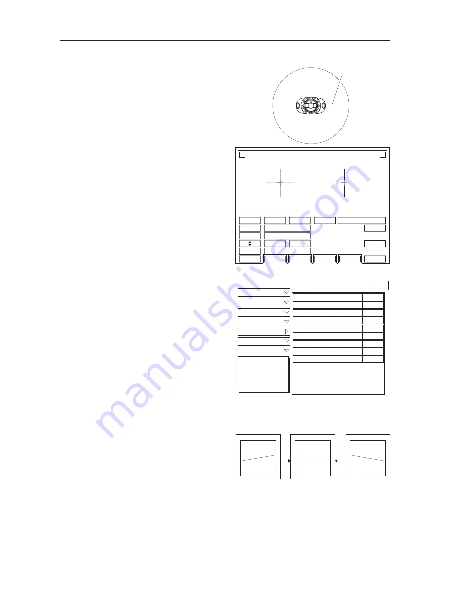
7.7 AXIS Adjustment
1. Draw a horizontal line in the middle of the
lens.
2. Block the lens cup to the lens to align it to the
horizontal line.
3. Read the stored lens data of square 45.
(See 7.2.4.)
4. Select the processing settings as below on the
layout screen.
1) Frame type
a. In bevel processing: Metal
b. In flat processing: Nylor
2) Processing mode: Auto
3) Polishing: NONE
4) S.F.B.: NONE
5. After the processing, measure the axis of the
lens with a graph paper and verify that it is
within the specified value
±
0.7 degree.
6. Adjust it by following the procedures below
when it is out of the specification.
1) Establish the Parameter Setting mode.
(See 7.1.2.)
2) Press Adjustment.
3) Press AXIS Adjustment.
4) Adjust the parameter settings below.
* Use the lens suitable for each parameter in
the adjustment.
a. CR39/Hi Index, Bevel
b. CR39/Hi Index, Flat
c. Polyca/Acrylic/Trivex, Bevel
d. Polyca/Acrylic/Trivex, Flat
e. Glass, Bevel
f. Glass, Flat
* Enter the plus value when the horizontal line
slants to the right viewing from the front of
the lens.
* Change the parameter settings in
±
0.1
increments.
* The parameter adjustment of the Glass, Bevel
and Glass, Flat are only for the wheel type of
PLB-G.
* The lens, which have been ground once, can be ground again to check by decreasing the size
in 3. However, finally verify that the axis angle does not displace when the size is 0.00.
* Use the lens cup for a half-eye lens not a pliable cup for the NIDEK cup specification.
*QTK\QPVCNNKPG
%4
5K\G
㪧㪛
㪝㪧㪛
&KURNC[
4+)*6
.'(6
/GVCN
#WVQ
2QNKUJ
'ZVGTP
010'
#EVKXG
㪤㪜㪥㪬
4
.
ь
Ǿ
ь
Ǿ
(2&%748'#0).'
%QXGT
4QWIJ5K\G
(KPKUJ5K\G
2QNKUJ5K\G
2QNKUJ&KHH
#:+5
5CHGV[$GXGN
)TQQXG&TKNN
Adjustment
%4*K+PFGZ$GXGN
%4*K+PFGZ(NCV
%4*K+PFGZ)TQQXG
2QN[EC#ET[NKE6TKXGZ$GXGN
2QN[EC#ET[NKE6TKXGZ(NCV
2QN[EC#ET[NKE6TKXGZ)TQQXG
)NCUU$GXGN
)NCUU(NCV
2QNKUJ
%4*K+PFGZ$GXGN
%4*K+PFGZ(NCV
%4*K+PFGZ)TQQXG
2QN[EC#ET[NKE6TKXGZ$GXGN
2QN[EC#ET[NKE6TKXGZ(NCV
2QN[EC#ET[NKE6TKXGZ)TQQXG
)NCUU$GXGN
)NCUU(NCV
2QNKUJ
BACK
Summary of Contents for ME-1000
Page 8: ...1 2 LLE11ARDA001A E...
Page 12: ...3 2 LLE11ARDA001A E...
Page 120: ...7 34 LLE11ARDA001A E...
Page 121: ...8 1 LLE11ARDA001A E 8 SUPPLEMENT 8 1 Wiring Diagram...
Page 122: ...8 2 LLE11ARDA001A E 8 2 Connector Cable...
Page 123: ...8 3 LLE11ARDA001A E...
Page 125: ...8 5 LLE11ARDA001A E 8 4 Labels Top view Processing chamber...
Page 126: ...8 6 LLE11ARDA001A E Rear view or...


