Upgrading Your System 4-31
Removable Media Devices
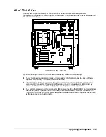
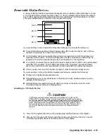
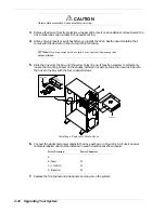
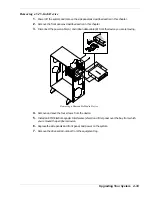
A variety of IDE and SCSI removable media devices can be installed in peripheral bays A, B, and
C. An IDE CD-ROM is always mounted in bay C. A 3.5-inch diskette drive is always mounted in
bay D. Other devices should be installed in the first available bay from the top (bay A). Contact
your sales representative or dealer for a list of approved devices.
BAY A
BAY B
BAY C
BAY D
If you are adding or removing an IDE removable media device, consider the following:
n
The system board supports a primary and secondary IDE channel connector. Each of these
supports two devices, for a total of four IDE devices.
n
A first (master) device and a second (slave) device are supported on both the primary and
secondary IDE connector. The device configuration, master versus slave, is determined by
jumpers on the device. Cable Sense (CS) device configuration is not supported.
n
Your system includes a three-connector IDE cable connecting the CD-ROM to the system board
secondary IDE connector. The CD-ROM that comes with your system is set as the master
device. A second IDE connect is available to connect a slave IDE removable media device.
n
If only one device is on an IDE channel connector it must be set as the master device.
If you are adding or removing a SCSI removable media device, consider the following:
n
The tape drive SCSI address assignment is 2.
n
If the SCSI tape is your only SCSI device on the SCSI controller, SCSI termination must be
installed in the tape drive.
n
If the SCSI tape is connected along with SCSI hard drives on the SCSI controller, SCSI
termination must be removed in the tape drive.
Installing a 5.25-Inch Device
CAUTION
CD-ROM devices contain a laser system and are classified as CLASS 1 LASER
PRODUCTS. To use these devices, thoroughly read the documentation provided by
the CD-ROM manufacturer, and keep the documentation for future reference. In case
of any trouble with a CD-ROM, please contact your nearest service representative. To
prevent direct exposure to the laser beam, do not try to open the enclosure. Use of
controls or adjustments or performance of procedures other than those specified in
the CD-ROM manufacturer's documentation may result in hazardous radiation
exposure
1.
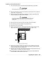
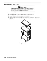
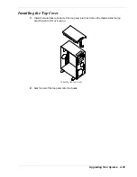
Power off the system and remove the side panels as described earlier in this chapter.
2.
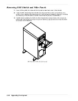
Remove the front panel, EMI shield, and filler panel covering the bay into which you are
installing a peripheral device as described earlier in this chapter.
Summary of Contents for EXPRESS 5800 ES1400 SERIES Online
Page 1: ...EXPRESS5800 ES1400 SERIES ONLINE SERVICE GUIDE...
Page 8: ...Using This Guide xv...
Page 21: ......
Page 33: ...2 12 Setting Up the System...
Page 60: ...Configuring Your System 3 27...
Page 130: ...Problem Solving 5 21...
Page 131: ......
Page 132: ......
Page 142: ...6 10 Illustrated Parts Breakdown...
Page 149: ...System Cabling A 7 WIDE SCSI CABLE 68 pins IDE CABLE 40 pins Standard System Cable Routing...
Page 160: ...System Setup Utility B 9 Adding and Removing ISA Cards Window...
Page 163: ...B 12 System Setup Utility System Resource Usage Window...

